
Constant-current constant-voltage charge control circuit

A charging control, constant current and constant voltage technology, applied in the direction of battery circuit devices, circuit devices, control/regulation systems, etc., can solve the problems of difficult compensation, complex voltage clamping circuit, and inaccurate clamping voltage, etc., and achieve low cost , The circuit realizes the effect of simple and accurate setting of the clamping value

Inactive Publication Date: 2013-03-13
深圳鼎信芯微电子有限公司
View PDF5 Cites 19 Cited by
  • Summary
  • Abstract
  • Description
  • Claims
  • Application Information

AI Technical Summary

Problems solved by technology

[0003] Commonly used voltage clamping circuits include circuits using Zener diodes. Once the model is selected, the clamping voltage value cannot be adjusted. In addition Figure 4 Two kinds of voltage clamping circuits are listed. The circuit V1 shown in (b) in the figure is the input voltage, and Vclamp is the voltage to be clamped. When V1 is higher than Vset, Vclamp will be clamped. When V1 is lower than Vset Vclamp is equal to V1, the clamping voltage Vclamp=Vset-Vth of the circuit shown in (a) in the figure, Vth is the threshold voltage of PMOS, this voltage will change with the process, temperature and other parameters, leading to the clamping voltage is not accurate
The voltage clamping circuit on the right is too complicated. If it is used in the loop, more poles and zeros will be added, making compensation difficult.

Method used


Image

  • Constant-current constant-voltage charge control circuit
  • Constant-current constant-voltage charge control circuit
  • Constant-current constant-voltage charge control circuit

Examples


Embodiment Construction

[0020] In order to make the object, technical solution and advantages of the present invention clearer, the present invention will be further described in detail below in conjunction with the accompanying drawings and embodiments. It should be understood that the specific embodiments described here are only used to explain the present invention, not to limit the present invention.

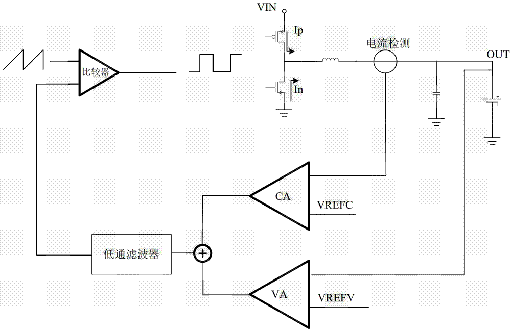
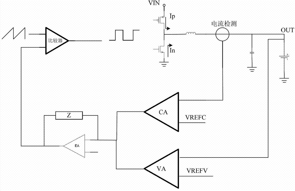
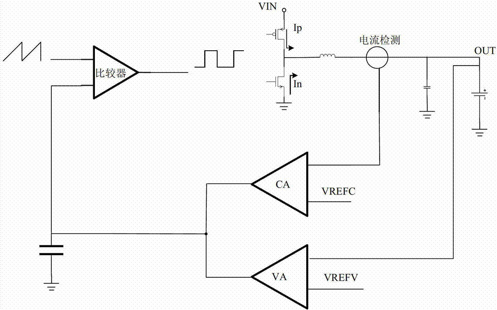
[0021] In view of the defects caused by the need to use 3 error amplifiers EA or large capacitors in the prior art, the purpose of the present invention is to provide a novel circuit architecture for replacing figure 1 shown in the circuit architecture, the circuit can achieve figure 1 The constant current and constant voltage charging function of the architecture, and the circuit is simple and easy to analyze and debug. At the same time, when developing a new circuit, it is necessary to use an accurate voltage clamping circuit to realize the constant current function, and the currently known circu...


PUM


Abstract

The invention discloses a constant-current constant-voltage charge control circuit. The circuit comprises a first metal oxide semiconductor field effect transistor (MOSFET), a second MOSFET, an inductor, a capacitor, a comparator, a first error amplifier, a second error amplifier, a voltage clamp circuit and a first compensating network, wherein the inverted input end of the first error amplifier is connected to the positive end of a battery and the normal phase input end of the first error amplifier is connected to a first reference voltage; one end of the voltage clamp circuit is connected to the output end of the first error amplifier and the other end of the voltage clamp circuit is connected to the normal phase input end of the second error amplifier; the inverted phase input end of the second error amplifier is connected to the signal output end of a current detecting unit connected in series onto a current path of the inductor; the output end of the second error amplifier is connected to the input end of the comparator; and the other input end of the comparator is connected with a sawtooth generator, and the first compensating network is connected between the inverted phase input end and the output end of the second error amplifier. According to the circuit, an external capacitor is not needed, the clamp value is set accurately, the circuit is simple, and the cost is low.

Description

technical field [0001] The invention belongs to the field of constant current and constant voltage charging, and more specifically relates to a constant current and constant voltage charging control circuit. Background technique [0002] At present, constant voltage and constant current charging is an important charging method: when the battery voltage is low, the constant current method is used for fast charging, and when the battery is close to saturation, the constant voltage method is used for trickle charging. Two loops are required to control the system, one is the current control loop for constant current charging, such as figure 1 The error amplifier CA used for current loop control, one end is connected to the detected inductor current feedback signal, and the other end is connected to the reference voltage; the other is a voltage control loop for constant voltage charging, such as figure 1 In the error amplifier VA used for voltage loop control, one end is connect...

Claims


Application Information

Patent Timeline
IPC IPC(8): H02J7/00G05F1/565
Inventor 冯稀亮徐卓慧
Owner 深圳鼎信芯微电子有限公司
Learn More