Device and method for measuring crossed plane electrical impedance tomography

A technology of imaging measurement and planar resistance, which is applied in diagnostic recording/measurement, medical science, diagnosis, etc. It can solve the problems that the range of 2~3 cm can only be guaranteed, the target position of the reconstructed image is difficult to judge, and the algorithm cannot be afforded. , to achieve the effect of strong anti-interference ability, small measurement drift and improved flexibility

Inactive Publication Date: 2013-03-20
SICHUAN SCI CITY DIWEI ELECTRIC
View PDF2 Cites 30 Cited by
  • Summary
  • Abstract
  • Description
  • Claims
  • Application Information

AI Technical Summary

Problems solved by technology

In traditional electrical impedance tomography, the placement of electrodes is usually limited to a certain plane. However, electrical impedance imaging is essentially a three-dimensional problem, and its current is not limited to flow on a certain plane. Therefore, two-dimensional image reconstruction is usually will produce artifacts
The main problem of 3D electrical impedance imaging is that the system cannot afford complex algorithms, and

Method used


Image

  • Device and method for measuring crossed plane electrical impedance tomography
  • Device and method for measuring crossed plane electrical impedance tomography
  • Device and method for measuring crossed plane electrical impedance tomography

Examples


Embodiment 1

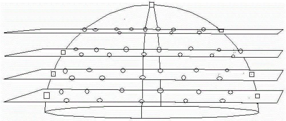
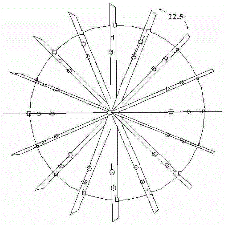
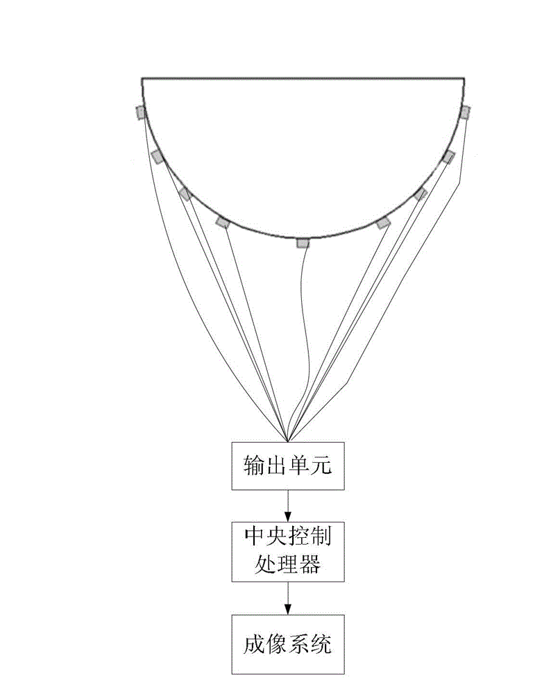
[0056] figure 1 Is a schematic side view and a top view of the cross-plane electrode arrangement of the present invention, figure 2 Is a schematic side view and a top view of the cross-plane electrode arrangement of the present invention, image 3 Is a schematic diagram of an application model of the present invention, Figure 4 Is a schematic diagram of the measuring electrode used in the present invention, Figure 5 It is a block diagram of the system principle of the present invention, as shown in the figure: a cross-plane electrical impedance imaging measurement device provided by the present invention includes a frame, measuring units and output units distributed on the frame, and the measuring units are distributed A measuring electrode on the frame for acquiring a voltage signal caused by the excitation current on the surface of the object to be measured, and the measuring electrode inputs the acquired voltage signal to the output unit.

[0057] The frame body is a hemisphe...

Embodiment 2

[0070] The cross-plane electrical impedance imaging measurement device and measurement method are described in detail below:

[0071] Image 6 It is a schematic diagram of the principle of the mixed frequency excitation source generator of the present invention, Figure 7 Is a schematic diagram of the principle of digital phase-sensitive detection on the FPGA of the present invention, Figure 8 The first signal excitation and detection method formed for the arrangement of cross-plane electrodes based on the present invention, Picture 9 The second method of signal excitation and detection is formed for the top view of the cross-plane electrode arrangement based on the present invention, Picture 10 The signal excitation and detection method 2 formed for the front view of the cross-plane electrode arrangement based on the present invention, Picture 11 The third method of signal excitation and detection is formed based on the arrangement of the cross-plane electrodes of the present i...


PUM

PropertyMeasurementUnit
Maximum temperatureaaaaaaaaaa
Resistanceaaaaaaaaaa
Diameteraaaaaaaaaa

Abstract

The invention discloses a device and a method capable of preferably reconstructing three-dimensional electrical impedance distribution in an object and improving electric field space distribution nonuniformity through obtaining object surface voltage information in particular relating to human organ tissues such as heads and breasts. Through the adoption of the scheme, voltage information can be obtained from both a horizontal section and a vertical section and images on the sections are respectively combined to form a space three-dimensional graphic; and voltages between the rest positions can be also obtained through exciting any contact point on the surface and then a plurality of combined measuring methods are achieved to realize multi-algorithm extension and improve image accuracy. The design mainly comprises 65 special electrodes distributed on a hemispherical surface; with a high-performance FPAG (Field Programmable Gate Array) as core, functions such as exciting source control, digital frequency synthesis, multiplex control, high speed phase-sensitive detection, fast Fourier transformation and measuring signal demodulation are integrated in a single chip; and a circuit design capable of self-adaptively adjusting output impedance of a detected object is achieved.

Description

Technical field [0001] The invention relates to a contact and measurement device in electrical impedance measurement, in particular to an electrical impedance imaging measurement device and method for human organs and tissues. Background technique [0002] Electrical impedance imaging is a method that only needs to measure on the surface of an object and reconstruct the internal impedance distribution. It builds an electric field by injecting current into a target area, and then measures the voltage generated around the target. In traditional electrical impedance tomography technology, the placement of electrodes is usually limited to a certain plane. However, electrical impedance imaging is essentially a three-dimensional problem, and its current is not limited to flowing on a certain plane. Therefore, two-dimensional image reconstruction is usually Will produce artifacts. The main problem of three-dimensional electrical impedance imaging is that the system cannot afford compl...

Claims


Application Information

Patent Timeline
IPC IPC(8): A61B5/053
Inventor 冉鹏何为徐征李松浓
Owner SICHUAN SCI CITY DIWEI ELECTRIC
Why Eureka
Try Eureka