Biomass fuel crusher

A technology of biomass fuel and crusher, which is applied in the direction of grain processing, etc., can solve the problems of inconsistent crushing speed, no significant improvement in crushing effect, and increased energy consumption, so as to reduce equipment investment, improve shearing effect, reduce energy consumption and Effect

Inactive Publication Date: 2013-03-20
WUXI YAQING MACHINERY
View PDF10 Cites 6 Cited by
  • Summary
  • Abstract
  • Description
  • Claims
  • Application Information

AI Technical Summary

Problems solved by technology

The crushed biomass fuel can be smoothly sent to the boiler. The industry adopts a crusher for crushing. The structure of the crusher adopts a cutter shaft, so that the motor must run at high speed when crushing the material. In single-shaft crushing, a part of the material is usually smashed , because it is not the shearing between the knives, the crushing effect of the material is not ideal, and the crushing efficiency is low
[0004] The improvement for the above shortcomings is to use two cutter shafts for crushing, and more cutter shafts are also used to drive more motors, resulting in an increase in energy consumption, because the two cutter shafts are driven by different motors Driven, the crushing speed is inconsistent, resulting in uneven crushing, and the crushing effect is not significantly improved

Method used


Image

  • Biomass fuel crusher
  • Biomass fuel crusher
  • Biomass fuel crusher

Examples


Embodiment Construction

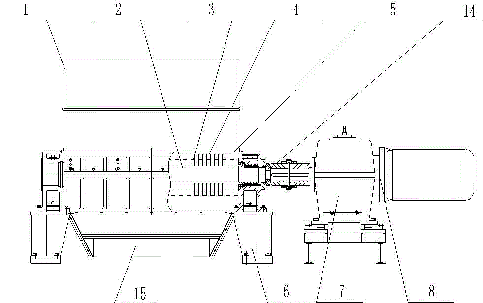
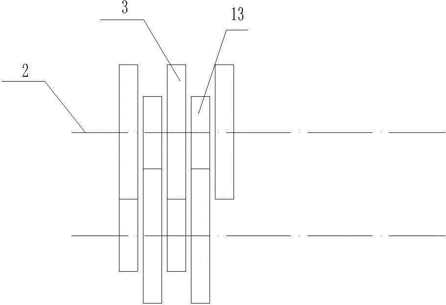
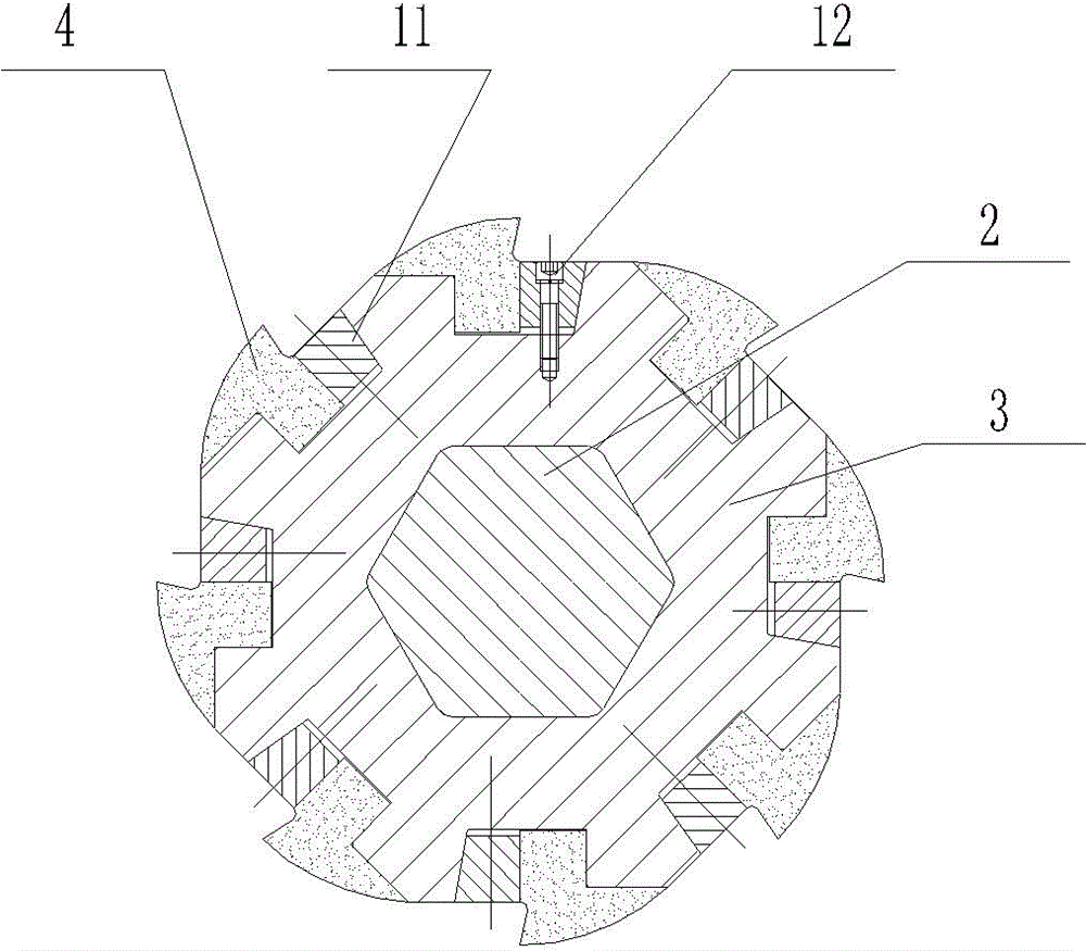
[0013] see figure 1 , The present invention includes a hopper 1, two knife shafts arranged side by side, including a driving knife shaft 2 and a driven knife shaft ( figure 1 In the main view, only the active tool axis 2 can be seen. The active tool axis 2 and the driven tool axis are respectively mounted on the bracket 6 ( figure 1 In the main view, only one cutter shaft can be seen), the active cutter shaft 2 and the driven cutter shaft have a sprocket 14 ( figure 1 In the main view, only one sprocket can be seen), the two sprocket gears are engaged, the sprocket 14 on the active cutter shaft 2 is connected to the reducer 7 through a coupling, and the reducer 7 is connected to the motor 8 at the outer end. , The two cutter shafts are respectively sleeved with cutter head 3, and the cutter heads 3 on the cutter shaft are embedded in each other and arranged axially at intervals (see figure 2 ), 13 is a spacer, which separates adjacent cutter heads and plays a role in positioning ...


PUM


Abstract

The invention provides a biomass fuel crusher. Energy consumption and investment of equipment are reduced by the biomass fuel crusher by reducing the number of driving motors, and at the same time, the biomass fuel crusher enables the crushing speed of cutter shafts to keep the same, and crushing effect is improved. The biomass fuel crusher comprises a hopper and two cutter shafts, wherein the two cutter shafts are arranged side by side and are respectively arranged on a support. One cutter shaft of the two cutter shafts is a driving cutter shaft. The driving cutter shaft is connected with gear reducers through a coupling. The gear reducers are respectively connected with an electrical machine. The two cutter shafts are respectively provided with a cutter head in a sleeved mode. The cutter heads on the two cutter shafts are mutually embedded into each other and are arranged at interval in a dislocated mode. A diffusion knife is arranged along the peripheries of the cutter heads. Rotating directions of the two cutter shafts are contrary to each other. When the two cutter shafts rotate, cutting edges of adjacent diffusion knives on the two cutter shafts are of shearing bite shapes. The lower portion of the hopper is connected with a retainer plate. The retainer plate is guided to cutter head meshed mouths of the two cutter shafts. The biomass fuel crusher is characterized in that one ends of the two cutter shafts are respectively connected with a chain wheel. Gears of the two chain wheels are meshed with each other.

Description

Technical field [0001] The invention relates to a crushing equipment for wastes such as straw, fruit tree branches and bark, waste wood, leftovers, etc., used in agriculture and forestry production, specifically a biomass fuel crusher. Background technique [0002] Waste straw, fruit tree branches and forestry production waste wood, tree branches, bark, etc., are all precious biomass fuels, which can be used as fuel for boilers. After being burned in the boiler, steam is generated for use Power generation and heating. Biomass fuel is a renewable energy source. Actively using biofuels to replace some primary energy sources such as petroleum and coal has obvious social and economic benefits for reducing primary energy consumption, reducing environmental pollution, and increasing farmers’ income. [0003] Biomass fuel must be crushed before being sent to the boiler for combustion. The crushed biomass fuel can be fed into the boiler smoothly. The crusher is used in the industry for c...

Claims


Application Information

Patent Timeline
Patent Type & Authority Applications(China)
IPC IPC(8): B02C18/14B02C18/18B02C18/24
Inventor 黄漪
Owner WUXI YAQING MACHINERY
Why Eureka
Try Eureka