Cooling-type needle valve coupling with carbon deposition prevention effect

A cooling type, anti-carbon technology, applied in the direction of engine components, machines/engines, charging systems, etc., can solve problems such as insufficient force, poor oil dripping and atomization, black smoke from diesel oil, etc., to improve service life, Good cooling effect, prevent serious carbon deposition effect

Active Publication Date: 2013-03-20
YUYAO SHUCHUN MACHINERY
View PDF4 Cites 9 Cited by
  • Summary
  • Abstract
  • Description
  • Claims
  • Application Information

AI Technical Summary

Problems solved by technology

[0003] When the diesel engine is working normally, the needle valve assembly of the injector is always in the state of high temperature, high pressure and high speed, and in this state, because the traditional needle valve assembly has no cooling water cavity and cooling channel for circulation, so It is easy to cause carbon deposits on the nozzle hole of the needle valve assembly in a high temperature environment, resulting in oil dripping and poor atomization
In the worst case, the diesel will emit black smoke due to incomplete combustion, resulting in insufficient power of the engine, waste of energy and environmental pollution. scrapped
[0004] Although the existing cooling needle valve coupler can reduce the temperature of the needle valve coupler, it is far from enough

Method used


Image

  • Cooling-type needle valve coupling with carbon deposition prevention effect
  • Cooling-type needle valve coupling with carbon deposition prevention effect
  • Cooling-type needle valve coupling with carbon deposition prevention effect

Examples


Embodiment Construction

[0022] Embodiments of the present invention will be further described in detail below in conjunction with the accompanying drawings.

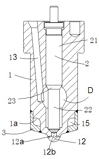
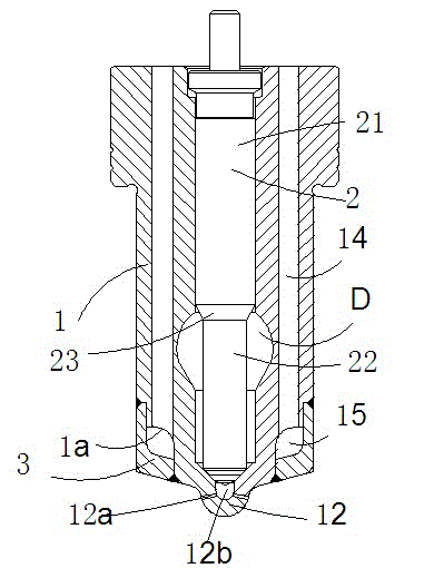
[0023] Figures 1 to 4 It is a schematic cross-sectional structure diagram of the present invention.

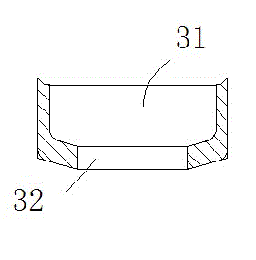
[0024] The reference signs are: needle valve body 1, annular surface 1a, valve cavity 11, nozzle body 12, nozzle hole 12a, nozzle cavity 12b, oil inlet passage 13, cooling ring 14, cooling chamber 15, needle valve 2 , Upper rod body 21, lower rod body 22, tapered transition section 23, cooling water jacket 3, cavity 31, shaft hole 32, annular gap channel D.

[0025] An anti-carbon deposition cooling needle valve coupler of the present invention comprises a matching needle valve body 1 and a needle valve 2, the needle valve 2 is assembled in the valve cavity 11 made of the needle valve body 1, and the needle valve Between the outer peripheral surface of the lower rod body 22 of 2 and the inner wall of the valve cavity 11, an annular gap chann...


PUM


Abstract

The invention discloses a cooling-type needle valve coupling with a carbon deposition prevention effect. The cooling-type needle valve coupling comprises a needle valve body and a needle valve, which are assembled with each other. The needle valve is assembled in a valve chamber which is machined in the needle valve body; an annular clearance passage, through which a high pressure fuel passes, is formed between the outer circumference of the lower rod body of the needle valve and the inner wall of the valve chamber; and the annular clearance passage is communicated with an oil inlet passage. The cooling-type needle valve is characterized in that a cooling water jacket is fixedly mounted to the lower part of the needle valve body, a cooling chamber is formed between the cooling water jacket and the needle valve body, the needle valve body is provided with at least one group of cooling annular passages, the cooling annular passages are communicated with the cooling chamber, the opening at the two ends of each cooling annular passage are formed in the upper surface of the needle valve body; at least two jet holes are formed in the front end of the needle valve body and are communicated with the annular clearance passage. The cooling-type needle valve coupling has the advantages of smart structure, good performance, low oil consumption, less carbon deposition in the nozzle and long service life and can meet the needs for oil-fuel injector needle-valve couplings in marine diesel engines.

Description

technical field [0001] The invention relates to a needle valve coupler of an internal combustion engine fuel injector, in particular to a cooling and environment-friendly needle valve coupler with an automatic cooling structure, in particular to a carbon deposit-proof cooling needle valve coupler. Background technique [0002] The fuel injector is an important component of the diesel engine. Its main function is to atomize the high-pressure diesel oil from the fuel injection pump according to certain requirements, and distribute it into the combustion chamber to form a good combustible mixture with the air entering the combustion chamber. As the core of the injector assembly, the needle valve coupling is a pair of precision couplings. The guide cylindrical surface on the upper part of the needle valve and the inner cylindrical surface of the needle valve make a high-precision sliding fit, and the requirements for the matching clearance and surface roughness are very high. Th...

Claims


Application Information

Patent Timeline
Patent Type & Authority Applications(China)
IPC IPC(8): F02M61/10F02M61/16
Inventor 舒学军
Owner YUYAO SHUCHUN MACHINERY
Why Eureka
Try Eureka