Recognition and location test method for noise sources

A technology for identifying positioning and testing methods, which is applied to measuring devices, measuring ultrasonic/sonic/infrasonic waves, instruments, etc., can solve the problems of increasing the number of array elements, unsatisfactory effects, and unrealistic effects, so as to reduce the distance between array elements and suppress Space aliasing, avoid mirror effect

Active Publication Date: 2013-03-20
BEIJING SHENZHOU PUHUI TECH
View PDF4 Cites 28 Cited by
  • Summary
  • Abstract
  • Description
  • Claims
  • Application Information

AI Technical Summary

Problems solved by technology

Under the premise of maintaining the aperture of the array elements, reducing the array element spacing requires increasing the number of array elements, which is not realistic in practical applications, and the effect is not ideal

Method used


Image

  • Recognition and location test method for noise sources
  • Recognition and location test method for noise sources
  • Recognition and location test method for noise sources

Examples


Embodiment 1

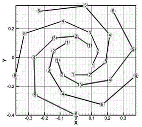
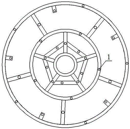
[0036] Embodiment 1, the microphone array of this embodiment is a wheel array with five wheel axles 1, the angle between every two wheel axles is 72°, the number of microphones 1, that is, the array elements is 30, and the coordinates of the wheel axles and array elements Figure such as figure 1 It can be seen from the figure that the array element points with the same number on each axle are located on different concentric circles with the center of the array as the center. When actually designing the external structure of the present invention, considering the stability and aesthetics of the microphone array structure, the microphone array is designed into two concentric outer rings with a pentagonal shape inside, such as figure 2 shown.

[0037] In the test, collecting data every 6° is equivalent to adding eleven virtual axles between the two axles, so that the number of array elements becomes 360.

[0038] When in use, the microphone array is fixed on the bracket. The b...

Embodiment 2

[0045] Example 2: Another embodiment of the present invention.

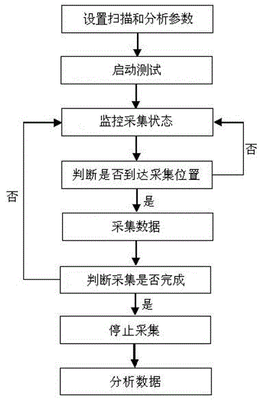
[0046] The difference between this embodiment and Embodiment 1 is that the scanning acquisition method of the microphone array adopts step-by-step scanning, that is, when the array rotates through an angular interval, it stops rotating and waits for the acquisition to be completed before continuing to rotate to complete the data acquisition. . The schematic flow chart of the steps of this embodiment is as follows Figure 4 shown.


PUM


Abstract

Disclosed is a recognition and location test method for noise sources. The method includes: (1) setting measurement parameters and analysis parameters on a main control computer (MCC); (2) performing sound wave scan collection of the noise sources through turning a microphone array, converting the obtained acoustical signals into electric signals, and obtaining real-time images of sound sources by using an optical camera fixed on the microphone array; (3) obtaining the electric signals in the step (2) through a data collector, and transmitting the signals to the MCC; and (4) the MCC performing data analysis on the electric signals, combining with images obtained by the optical camera to form and display a sonogram of the noise sources. Fast recognition and location for the noise sources can be achieved through the method, the testing accuracy can be improved remarkably compared with the existing noise source recognition technology, and noise testing of complex vibrational structural bodies can be finished rapidly and accurately.

Description

technical field [0001] The invention relates to the technical field of acoustics, in particular to a noise source identification and location testing method. Background technique [0002] In recent years, the noise source identification and positioning test technology has been widely used in the environmental noise detection of ships, aerospace, automobile industry, home appliance industry, power plant workshop and other noise detection fields of various mechanical equipment. By understanding the location distribution and part of the noise source Sound characteristics provide a theoretical basis for reducing noise, and then improve product design, improve product sound radiation characteristics, and achieve vibration and noise reduction effects. The traditional noise source identification and positioning test method uses an array composed of a group of microphones distributed in fixed spatial positions to measure the spatial signal, and then measures and analyzes the sound f...

Claims


Application Information

Patent Timeline
Patent Type & Authority Applications(China)
IPC IPC(8): G01H9/00
Inventor 张若愚聂佳申和平
Owner BEIJING SHENZHOU PUHUI TECH
Why Eureka
Try Eureka