PWM strategy for reduction of inverter hotspot temperature and overall losses

一种脉冲宽度调制、方案的技术,应用在控制驱动、控制系统、控制装置等方向,能够解决效果有限等问题

Active Publication Date: 2013-03-27
FORD GLOBAL TECH LLC
View PDF4 Cites 7 Cited by
  • Summary
  • Abstract
  • Description
  • Claims
  • Application Information

AI Technical Summary

Problems solved by technology

Although this solution can reduce the switching losses of the inverter, its effect is limited since conduction losses usually dominate the losses in the power device

Method used


Image

  • PWM strategy for reduction of inverter hotspot temperature and overall losses
  • PWM strategy for reduction of inverter hotspot temperature and overall losses
  • PWM strategy for reduction of inverter hotspot temperature and overall losses

Examples


Embodiment Construction

[0021] Exemplary embodiments of the invention are described herein; however, the invention may be practiced in various alternative ways, as will be apparent to those skilled in the art. To facilitate an understanding of the invention and provide a basis for the claims, the description includes several drawings. In order to emphasize the novel features of the invention, the drawings are not drawn to scale and related elements have been omitted. Structural and functional details depicted in the figures are for the purpose of teaching those skilled in the art to practice the invention and are not to be construed as limitations. For example, the control modules and elements in the various systems may be arranged and / or combined differently and should not be considered limited to the exemplary configurations presented here.

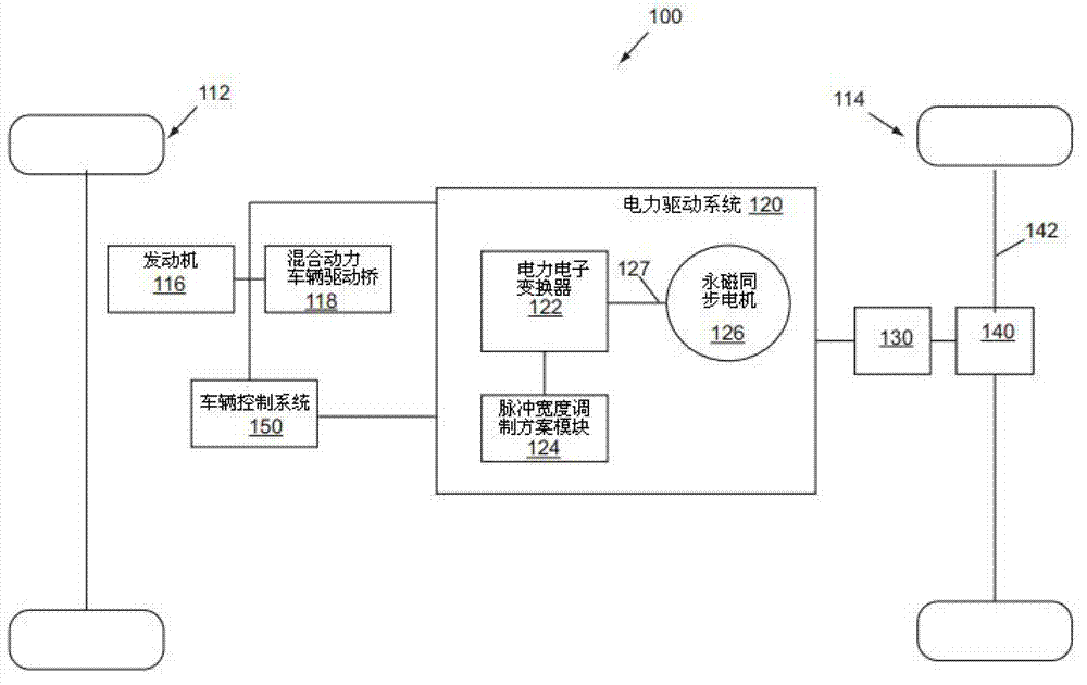
[0022] figure 1 A schematic diagram illustrating an example vehicle 100 is shown. Vehicle 100 may be of any suitable type, such as an electric vehicle or a...


PUM


Abstract

The invention provides a PWM strategy for reduction of inverter hotspot temperature and overall losses. The PWM strategy can be implemented to reduce device power losses and hotspot temperature in an inverter circuit that drives a synchronous motor. A method includes migrating a phase current from a power device with higher losses to a power device with lower losses. A PWM modulation signal can be modified to alter the inverter duty cycle and migrate phase current in the direction of lower losses. As an example, a PWM reference signal can be shifted to a lower value. A PWM loss reduction strategy can be performed while a motor is in a rotor-lock state to reduce device hotspot temperature. The PWM loss reduction strategy can also be performed when a motor is operating in a normal state, pushing PWM to DPWM, reducing switching and overall losses. The strategy can be practiced while a PMSM is operating as a motor, and can also be practiced during regenerative braking.

Description

technical field [0001] The present invention relates to electronic inverters, and more particularly to a method and apparatus for reducing hotspot temperature and power loss of power devices in electronic inverters for permanent magnet synchronous motors (PMSM). Background technique [0002] Electric machines, such as electric vehicles or hybrid vehicles, can be propelled using electrical energy through an electric drive system, which can include a power circuit, such as an electronic inverter, connected to an electric motor. In this configuration, the power supply circuit controllably transfers power from the power supply to the electric motor to drive a load, such as a vehicle transaxle. For a three-phase synchronous motor, the power circuit may include an inverter with three phase legs, each leg including a switch that can be individually controlled to provide the desired inverter output. For example, a drive signal as a function of the torque demand of the electric moto...

Claims


Application Information

Patent Timeline
Patent Type & Authority Applications(China)
IPC IPC(8): H02P6/08H02M7/5395B60L50/16
CPCH02P27/085H02P29/027Y02T90/34B60L2240/423Y02T10/7022H02P6/14H02M2001/327Y02T10/7241B60L3/003B60L2210/40B60L2240/525B60L2240/527B60L15/2009H02M1/32B60L11/005B60L15/007B60L11/1887H02P29/0088H02M7/53871Y02T10/644H02M2001/0054B60L11/14Y02T10/7077B60L2240/529B60L2220/14Y02T10/70H02P29/68B60L50/40B60L50/16B60L58/40Y02T10/64Y02T10/72Y02T10/7072H02M1/0054H02M1/327Y02T10/92Y02T90/40
Inventor 陈礼华陈清麒迈克尔·W·德格尼尔沙拉姆·萨雷
Owner FORD GLOBAL TECH LLC
Why Eureka
Try Eureka