
Calibration method and flow-rate measurement method for flow-rate controller of gas supplying apparatus

A technology of flow controller and gas supply, which is applied in flow control of electric devices, flow control, measurement flow/mass flow, etc. It can solve the problems of unavoidable flow calculation error and time-consuming volume V in the flow path, and achieve simple Effects of flow correction, rapid flow correction, and high-precision flow correction

Active Publication Date: 2013-03-27
FUJIKIN INC
View PDF7 Cites 24 Cited by
  • Summary
  • Abstract
  • Description
  • Claims
  • Application Information

AI Technical Summary

Problems solved by technology

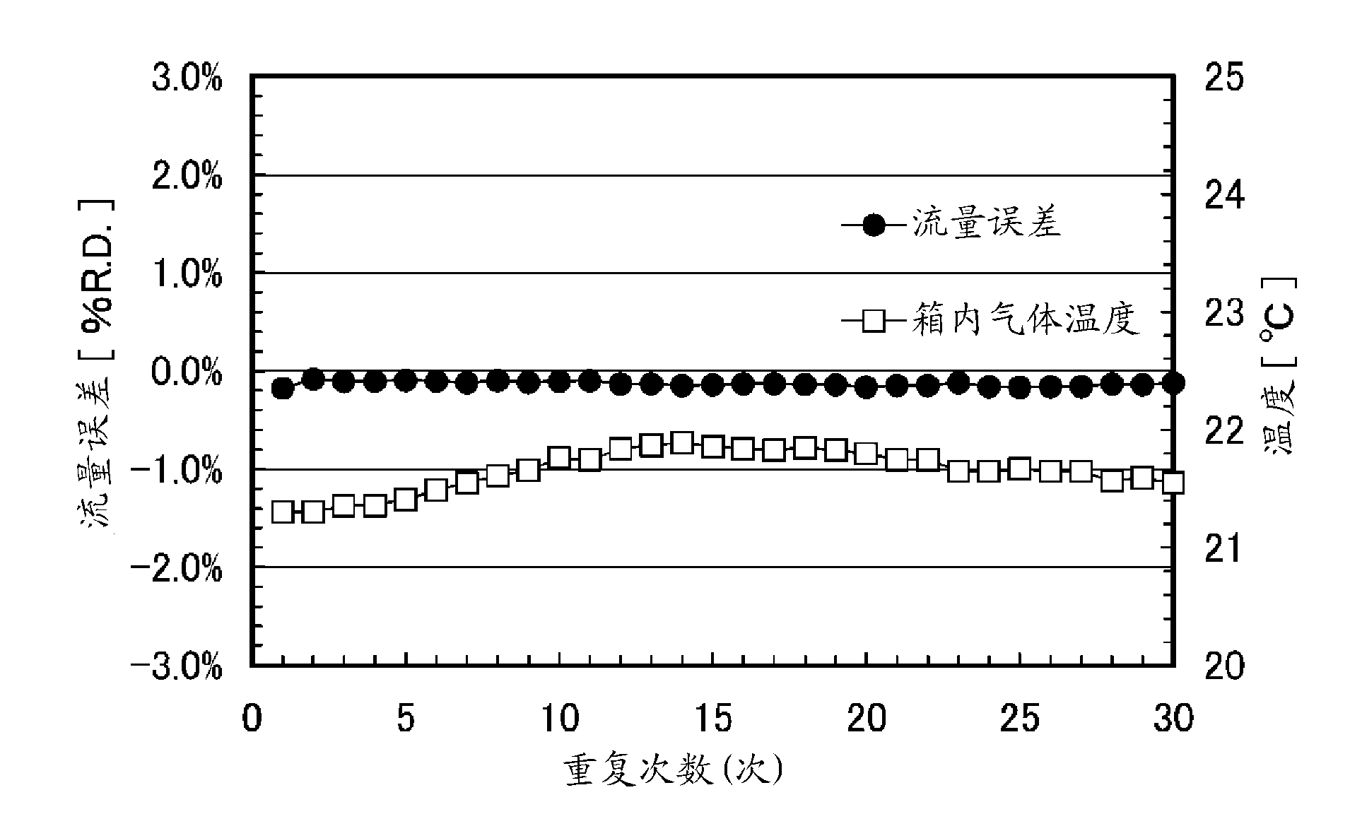
[0016] The invention of the present application addresses the above-mentioned problems in the conventional flow controller calibration method and flow measurement method by the accumulation or ROR method, that is, (1) using the accumulation tank whose internal volume is known in advance based on the pressure increase rate ΔP In the method of correcting the control flow rate by / Δt and time Δt, the calculation error of the flow rate due to the fluctuation of the gas temperature during the pressure increase cannot be avoided. In addition, (2) Supply a constant flow rate to the flow path with the total internal volume V In the method of calculating the flow rate Q by calculating the difference ΔG of the mass of gas flowing into the flow path V during a certain time interval Δt, it is first necessary to obtain the volume V in the flow path by some method, and Compared with the case of using the accumulating tank BT whose internal volume is known, there is a problem that the calculation of the internal volume V of the flow path takes too much effort.

Method used


Image

  • Calibration method and flow-rate measurement method for flow-rate controller of gas supplying apparatus
  • Calibration method and flow-rate measurement method for flow-rate controller of gas supplying apparatus
  • Calibration method and flow-rate measurement method for flow-rate controller of gas supplying apparatus

Examples


no. 1 Embodiment approach

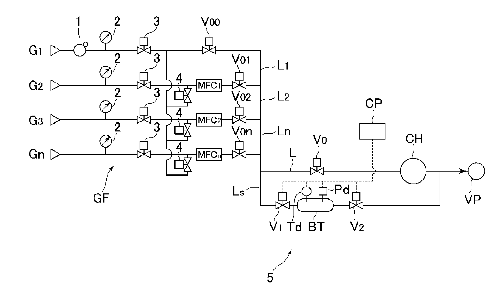
[0058] refer to figure 1 and figure 2 , when calibrating the flow rate of the flow controller of the gas supply device GF, the flow controller calibrating unit 5 is first connected to the gas supply line L in a branched form. Next, in the flow controller MFC 1 correction, will open and close the valve V 00 , V 02 , V 0n , V 0 Closed, open and close the valve V 01 , V 1 , V 2 Open, from flow controller MFC 1 The gas flow of the set flow rate Qs is supplied to the calibration unit 5 and exhausted by the vacuum pump VP.

[0059] Next, if the gas temperature To and the gas pressure Po in the accumulating tank BT of the calibration unit 5 are stabilized, the outlet side on-off valve V 2 It is closed to start accumulation of gas, and the gas temperature To and gas pressure Po in the box are detected and input to the calculation control unit CP.

[0060] Progress towards the accumulation of gas inside the tank BT, if the gas pressure reaches the set value P 1 (or set th...

no. 2 Embodiment approach

[0077] In the second embodiment, since the internal capacity of the accumulation tank BT is as small as 120.36 cc, first, the relationship between the supply flow rate and the tank internal pressure was investigated.

[0078] Figure 6 is a graph showing the results of this investigation, and Figure 7 yes Figure 6 A magnified view of part A.

[0079] Depend on Figure 6 and Figure 7 It can also be seen that when the internal volume of the accumulation tank BT is about 120.36cc, the gas supply flow rate is 1.6SLM, and the internal pressure rises to about 100Torr (opening and closing valve V 1 , V 2It is an on-off valve with a Cv value of 0.1). In addition, T1000 is a calibrated flow controller adjusted by the above-mentioned calibrated flow control equipment, etc.

[0080] On the other hand, there are thermal flow controllers or pressure flow controllers among flow controllers to be corrected, and in the case of pressure flow controllers, the pressure value on the out...

no. 3 Embodiment approach

[0100] Figure 11 It is a system diagram of the flow controller calibration unit used in the third embodiment of the present invention, T1000 is the calibrated flow controller adjusted by the calibrated flow control device, etc., ST is the waste chamber, and V 1 is the on-off valve on the inlet side of the accumulation tank BT, V 1S is the on-off valve on the inlet side of the waste chamber, V 2S It is the on-off valve on the outlet side of the waste chamber. In addition, of course, the inlet side on-off valve V 1 and V 1S Replaced with double three-way valve (two-connected three-way valve) V 3 And use.

[0101] In the flow calibration and flow measurement of the flow controller, it is necessary to keep the gas flowing for a certain period of time from the vacuum state to the flow, pressure, and temperature stabilization. It takes a long time until the gas is stable, and the gas flow is large. In the case where, for example, a gas with a flow rate of several LSM to sever...


PUM


Abstract

Flow-rate calibration is executed, by opening just an exit-side opening / closing valve of a flow-rate controller to be calibrated and letting gas with a set flow-rate flow into a calibration unit (5), measuring, at time (t0) when gas temperature and gas pressure within a tank (BT) has stabilized, the gas temperature (T0) and the gas pressure (P0) within the tank (BT) for the first time, then closing an exit-side opening / closing valve (V2) of the calibration unit (5) to build up gas within the tank (BT), closing an entrance-side opening / closing valve (V1) of the calibration unit (5) at time (t1) and measuring the gas temperature (T2) and the gas pressure (P2) within the tank for the second time at time (t2), which is subsequent to the closing of the entrance-side opening / closing valve (V1), calculating the gas flow-rate (Q) from the measured values with a formula of Q = (22.4V / R DEG.t); (P2 / T2-P0 / T0) (wherein V is the internal volume of the tank (BT), R is the gas constant, and t is the build-up time (t1 - t0)), and comparing the gas flow rate that was set and the calculated as flow rate (Q).

Description

technical field [0001] The present invention relates to the improvement of the calibration method and the flow measurement method of the flow controller of the gas supply device used in the semiconductor manufacturing equipment and the pharmaceutical manufacturing equipment, etc., and relates to the flow calibration and the flow rate which can be performed quickly and with higher accuracy in a short time. Calibration method and flow measurement method of flow controller for gas supply device for measurement. Background technique [0002] A gas supply device such as a semiconductor manufacturing device generally has a structure in which a plurality of gases are switched and supplied to a gas user such as a processing chamber, and the gas whose flow rate is controlled by a flow controller provided for each type of supplied gas is supplied to the gas user. [0003] In addition, the flow rate calibration and flow measurement of the above-mentioned flow controllers are generally ...

Claims


Application Information

Patent Timeline
Patent Type & Authority Applications(China)
IPC IPC(8): G05D7/06G01F3/38G01F25/00
CPCG01F15/005G01F15/002G01F1/34G01F7/005G01F25/0053G05D7/0652Y10T137/0324G01F25/15G01F25/00G05D7/06
Inventor 永濑正明池田信一泽田洋平平井畅森崎和之西野功二土肥亮介
Owner FUJIKIN INC
Learn More