Directional solidification casting method of continuous cold crucible

A technology of directional solidification and cold crucible, applied in the field of directional solidification casting, can solve problems such as forming complex castings

Active Publication Date: 2013-04-03
HARBIN INST OF TECH
View PDF6 Cites 7 Cited by
  • Summary
  • Abstract
  • Description
  • Claims
  • Application Information

AI Technical Summary

Problems solved by technology

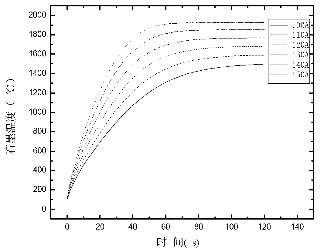
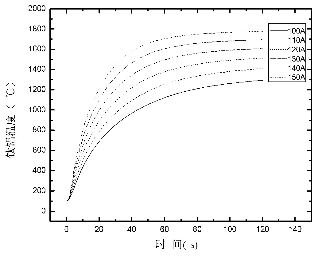
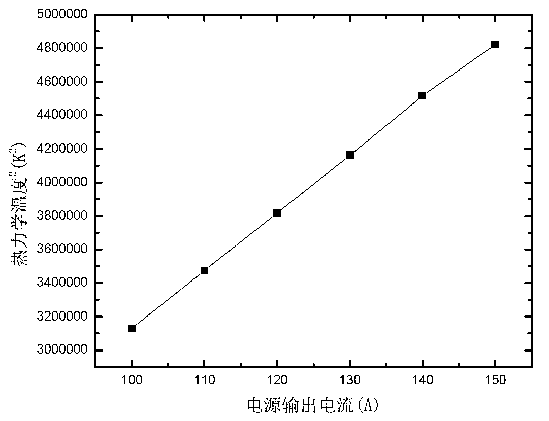
[0005] The purpose of the present invention is to provide a continuous cold crucible directional solidification casting method for titanium aluminum alloy, which can better solve the problem of forming complex castings, and at the same time clarify the current applied by the induction coil, the radius of the graphite heating element and the graphite induction. The relationship between the steady state temperature of heating has a positive effect on the research of directional solidification casting method

Method used


Image

  • Directional solidification casting method of continuous cold crucible
  • Directional solidification casting method of continuous cold crucible
  • Directional solidification casting method of continuous cold crucible

Examples


Embodiment 1

[0021] A continuous cold crucible directional solidification casting method, the water-cooled copper crucible in the electromagnetic cold crucible directional solidification device is placed in a closed furnace body, an electromagnetic induction coil is arranged outside the water-cooled copper crucible, and the lower end of the bar material is extended in the water-cooled copper crucible , the crystallizer containing the coolant material is placed directly below the water-cooled copper crucible, and a lower drawing rod is arranged in the crystallizer, and a mold shell is fixed on the upper end of the lower draw rod, and the mold shell is a ring-shaped transparent up and down Shell, the lower end edge of the ring-shaped shell is fixed on the lower drawing rod through the connecting rod, and the bottom material is pre-set in the ring-shaped shell at the upper end of the lower drawing rod. The outer surface of the mold shell is provided with a circular graphite heating element wit...

Embodiment 2

[0029] The induction coil described in this embodiment is made of a T3 copper tube with an outer diameter of 9.5 to 10.5 mm and an inner diameter of 5.5 to 6.5 mm. 4 turns for a coil of 134-140mm. The bar stock is titanium-aluminum alloy bar stock, the input current of the coil is 150A, the output power of the power supply is 45-55kW, the upper feeding speed is set at 1mm / min, the pulling speed of the lower drawing rod is 1.6-1.9mm / min, and the holding time 12~18min, the pulling distance is 60~80mm. The shape of the upper hump is close to hemispherical, and the melting state is good.


PUM

PropertyMeasurementUnit
Outer diameteraaaaaaaaaa
The inside diameter ofaaaaaaaaaa
Outer diameteraaaaaaaaaa

Abstract

The invention discloses a directional solidification casting method of a continuous cold crucible. According to the directional solidification casting method, a water-cooled copper crucible in a directional solidification device of an electromagnetic cold crucible is arranged in a closed furnace body, wherein an electromagnetic induction coil is arranged outside the water-cooled copper crucible; the lower end of a bar extends into the water-cooled copper crucible; a crystallizer filled with a coolant material is arranged under the water-cooled copper crucible; a pull-down rod is arranged in the crystallizer; a formwork is fixed at the upper end of the pull-down rod; a circular graphite heating element, having a height of 55-65mm, an outer diameter of 55-65mm and an inner diameter of 40-50mm, is arranged outside the formwork; a thermal insulation layer is covered outside the graphite heating element; an induction coil is arranged outside the thermal insulation layer; and a graphite induction heating steady-state temperature is determined by the formula (refer to the Specification), wherein I represents an input current, r represents the radius of a coil, epsilon is 0.9, and a is an empirical parameter 2816681. According to the directional solidification casting method of a continuous cold crucible, the relation between the output current and the thermodynamic temperature of the graphite is provided, and the basis for conveniently controlling the process parameters in actual use is provided.

Description

technical field [0001] The invention relates to a directional solidification casting method. Background technique [0002] With the vigorous development of industries such as aviation, aerospace and energy, traditional materials and material processing technology can no longer meet the demand, and the emphasis on new materials and new material processing technology is increasing. Among them, reducing the weight of engine structural components and increasing engine combustion temperature are effective ways to improve efficiency. At present, nickel-based superalloys and titanium alloys are commonly used in high-temperature components. The service temperature of titanium alloys reaches 600°C, and that of nickel-based superalloys is close to 1100°C. However, nickel-based superalloys have a high density, while titanium alloys have poor oxidation resistance at high temperatures. Therefore, finding a new type of alloy that is light, high-temperature resistant and highly reliable h...

Claims


Application Information

Patent Timeline
IPC IPC(8): B22D27/02
Inventor 丁宏升张海龙王永喆李明亮李建崇刘晨光南海
Owner HARBIN INST OF TECH
Why Eureka
Try Eureka