Thermal transfer sheet
A technology of thermal transfer printing and sheet materials, applied in printing, printing devices, copying/marking methods, etc., can solve the problems of complex manufacturing process, low productivity, increased production cost, etc., and achieve low bleeding, high sensitivity, The effect of excellent blocking resistance
- Summary
- Abstract
- Description
- Claims
- Application Information
AI Technical Summary
Problems solved by technology
Method used
Image

Examples
preparation example Construction
[0022] 2.1 Preparation of AS resin
[0023] 2.2 Synthesis of acrylic resin
[0024] 2.3 Preparation of mixed solution
[0025] 2.4 Coating and drying of mixed solution
[0026] [1. Composition of thermal transfer receiving sheet]
[0027] [1.1 Overall structure]
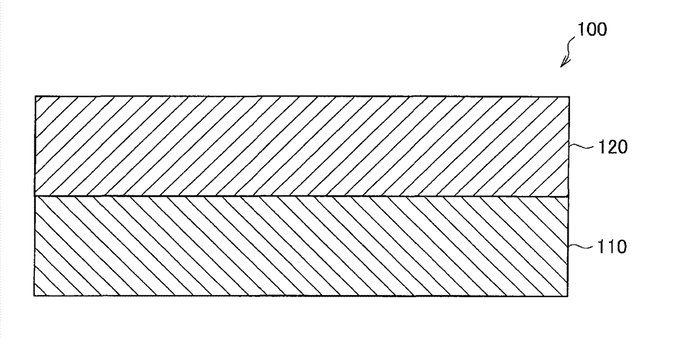
[0028] First, refer to figure 1 The general structure of the thermal transfer receiving sheet according to the preferred embodiment of the present invention is described. figure 1 It is a schematic cross-sectional view which shows the structure of the thermal transfer receiving sheet of the preferable embodiment of this invention.
[0029] like figure 1 As shown, the thermal transfer receiving sheet 100 according to the present embodiment includes a base sheet 110 and a dye receiving layer 120 formed on the base sheet 110 .
[0030] In general, the dye-receiving layer is formed using a polymer resin as a main component. In order to improve heat resistance, curing agents such as polyisocyanates may be added to...
Embodiment 1
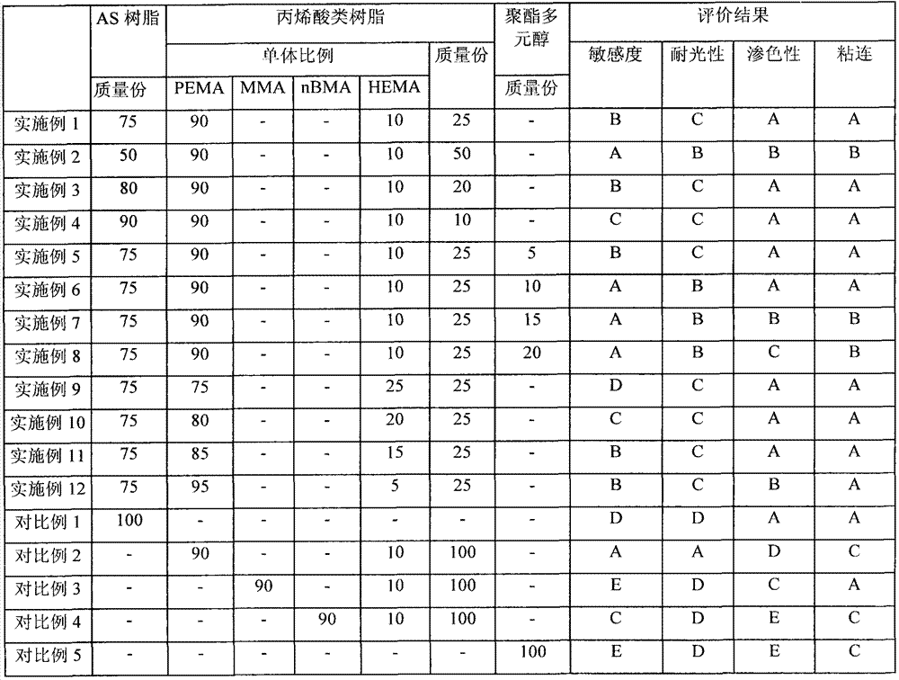
[0079] Based on the ratios listed in Table 1 below, AS-61 (a copolymer of styrene monomer and acrylonitrile monomer in a mixing ratio of 24:76) commercially available from Nippon Steel Chemical Co., Ltd. was used as the AS resin, A PEMA / HEMA copolymer was used as the acrylic resin. Then, AS resin and acrylic resin are mixed. Subsequently, the mixture was diluted with a mixed solvent of 2-butanone and toluene (mixing ratio of 1:1) so that the solid content of the mixture was 20% by mass, and then the thus obtained mixed solution for forming a dye-receiving layer was The mixed solution was applied to a synthetic paper of 150 μm (“YUPO FPG-150” commercially available from Oji Yuka) in an amount that could reach a thickness of 3 μm after drying, and dried at 120° C. for 1 minute to remove the solvent, thereby producing Examples 1 of the thermal transfer accepting sheets.
Embodiment 2 to 6 and comparative example 1 to 5
[0081] The thermal transfer receiving sheets of Examples 2 to 12 and Comparative Examples 1 to 5 were produced in the same manner as described in Example 1, except that the content of AS resin, the content of acrylic resin, the ratio of PEMA to HEMA The mixing ratio, the kind of the monomer of the acrylic resin, and the content of the polyester polyol were changed as listed in Table 1.
[0082] [Printing method using thermal transfer receiving sheet]
[0083] Using a thermal transfer printer (UP-DR200 printer commercially available from Sony Corporation) and an ink ribbon ( UPC-204 (commercially available from Sony Corporation) was printed on the thermal transfer receiving sheets of Examples 1 to 12 and Comparative Examples 1 to 6 manufactured as described above.
[0084] [Evaluation method of thermal transfer receiving sheet]
[0085] After printing, each thermal transfer receiving sheet was evaluated for sensitivity, light fastness, bleeding properties maintained at high t...
PUM
| Property | Measurement | Unit |
|---|---|---|
| Thickness | aaaaa | aaaaa |
| Thickness | aaaaa | aaaaa |
Abstract
Description
Claims
Application Information
 - R&D Engineer
- R&D Manager
- IP Professional
- Industry Leading Data Capabilities
- Powerful AI technology
- Patent DNA Extraction
Browse by: Latest US Patents, China's latest patents, Technical Efficacy Thesaurus, Application Domain, Technology Topic.
© 2024 PatSnap. All rights reserved.Legal|Privacy policy|Modern Slavery Act Transparency Statement|Sitemap