
Photon sieve and manufacturing method thereof

A production method and technology of photon sieves, applied in optics, diffraction gratings, optomechanical equipment, etc., can solve the problems of low diffraction efficiency of photon sieves, and achieve improved diffraction efficiency, increased transmittance, surface plasmon polarization and surface Effect of Plasma Coupling Enhancement

Active Publication Date: 2013-04-03
INST OF MICROELECTRONICS CHINESE ACAD OF SCI
View PDF3 Cites 6 Cited by
  • Summary
  • Abstract
  • Description
  • Claims
  • Application Information

AI Technical Summary

Problems solved by technology

[0005] In view of this, the present invention provides a photon sieve and a manufacturing method thereof to solve the problem of low diffraction efficiency of existing photon sieves

Method used


Image

  • Photon sieve and manufacturing method thereof
  • Photon sieve and manufacturing method thereof
  • Photon sieve and manufacturing method thereof

Examples


Embodiment 1

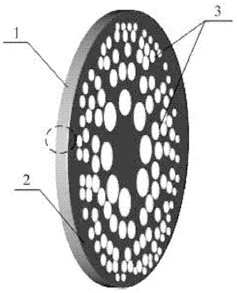
[0037] refer to figure 1 , figure 1 It is a schematic diagram of the structure of the photonic sieve provided by the present invention, the photonic sieve includes: a light-transmitting substrate 1; 2 includes a multilayer metal film and a dielectric film arranged alternately; a plurality of small holes 3 arranged on the opaque multilayer film 2 and distributed in a plurality of rings, and a plurality of small holes on each ring 3 are distributed randomly and do not overlap each other.

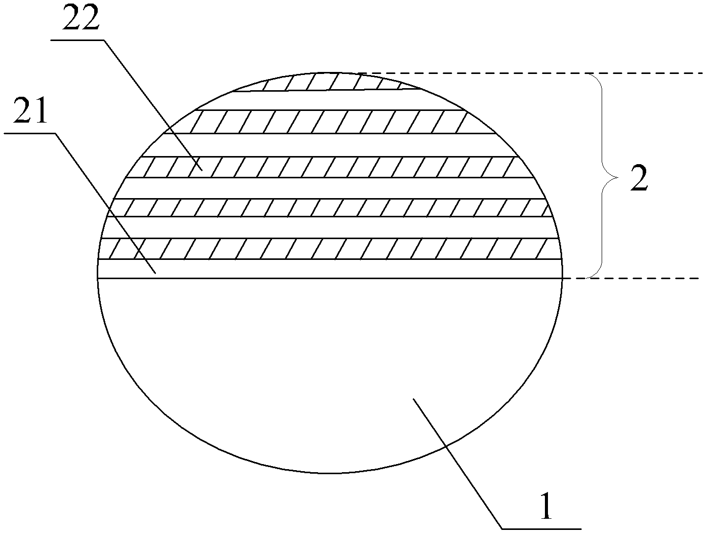
[0038] In order to more clearly describe the positional relationship between the light-transmitting substrate 1 and the opaque multilayer film 2 on it, the figure 1 The part of the dotted line frame in the middle is partially enlarged, and the obtained cross-sectional schematic diagram is as follows figure 2 as shown, figure 2 The figure shows a light-transmitting substrate 1 and an opaque multi-layer film 2 on the light-transmitting substrate 1 . The light-impermeable multi-layer film 2...

Embodiment 2

[0049] The photon sieve provided by the present invention has been described in detail above, and the manufacturing method of the photon sieve is introduced below.

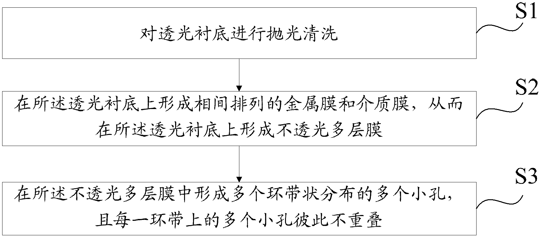
[0050] refer to image 3 , image 3 It is a schematic flow chart of the photon sieve manufacturing method provided by the present invention, and the method specifically includes the following steps:

[0051] Step S1: Polishing and cleaning the transparent substrate.

[0052] First, a light-transmitting substrate is selected, and the light-transmitting substrate is polished and cleaned. The light-transmitting substrate is selected as a quartz substrate, the thickness of the quartz substrate is 1.5mm, and the diameter is 25.4mm, and the transmittance of the light-transmitting substrate is greater than 85% under the irradiation of an applied wavelength of 405nm. After the light-transmitting substrate is polished and cleaned, the roughness of the light-transmitting substrate is less than 0.5 nm, and the flatness is l...


PUM

PropertyMeasurementUnit
thicknessaaaaaaaaaa

Abstract

The embodiment of the invention discloses a photon sieve and a manufacturing method thereof. The photon sieve comprises a light-transmitting substrate, a plurality of light-tight films and a plurality of small holes, wherein the plurality of light-tight films are located on the light-transmitting substrate and consist of a plurality of metal films and dielectric films at intervals; and the plurality of small holes are formed in the light-tight films and are distributed in a zonal shape, and a plurality of small holes in each girdle are randomly distributed and are not overlapped with one other. Because the plurality of metal films and dielectric films at intervals are arranged on the light-transmitting substrate, and the plurality of small holes distributed in the zonal shape are formed in the plurality of metal films and dielectric films at intervals, when light irradiates the a photon sieve, the surface plasma polarization and the surface plasma coupling of the metal films and the dielectric films are enhanced, the light transmittance is effectively improved, and further the diffraction efficiency of the photon sieve is improved.

Description

technical field [0001] The invention relates to the technical field of diffractive optical elements, and more specifically, to a photon sieve and a manufacturing method thereof. Background technique [0002] The photon sieve is a new type of diffractive optical element based on the Fresnel zone plate. It replaces the area corresponding to the bright ring on the Fresnel zone plate with a large number of randomly distributed light-transmitting small holes, and the diameter of the small holes is the corresponding 1.5 times the width of the zone plate ring. The photon sieve breaks through the resolution limit of the zone plate, and the obtained focused spot is smaller than that of the zone plate with the same characteristic size, and effectively suppresses the side lobe of the focused spot, reduces the background light and improves the resolution . [0003] Compared with zone plates, photonic sieves are simple to manufacture and superior in performance. They have good applicat...

Claims


Application Information

Patent Timeline
Patent Type & Authority Applications(China)
IPC IPC(8): G02B5/18G03F7/00
Inventor 李海亮史丽娜朱效立李冬梅谢常青刘明
Owner INST OF MICROELECTRONICS CHINESE ACAD OF SCI
Learn More