Topological insulator structure
A technology of topological insulators and insulating substrates, applied in inorganic chemistry, non-metallic elements, selenium/tellurium compounds, etc., can solve the problems of unmanufactured and unmanufactured topological insulators, achieve large anomalous Hall resistance, and realize quantization Anomalous Hall effect, the effect of reducing the carrier concentration
- Summary
- Abstract
- Description
- Claims
- Application Information
AI Technical Summary
Problems solved by technology
Method used
Image
Examples
Embodiment 1
[0069] Example 1 (T=30mK, 5QL sample, back gate control)
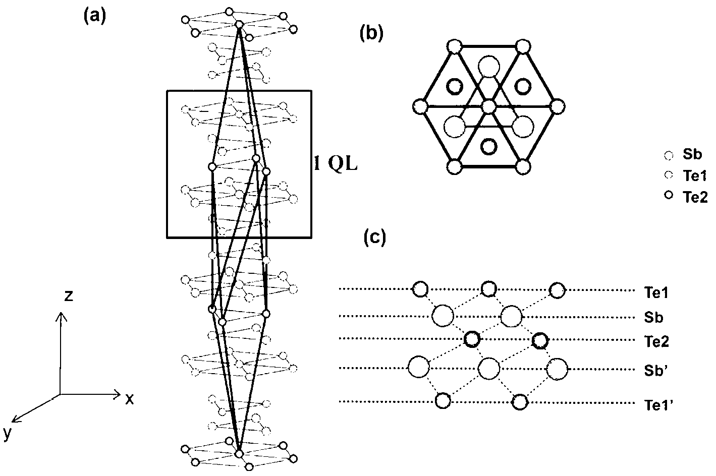
[0070] The magnetic doped topological insulator quantum well film is Cr 0.15 (Bi 0.10 Sb 0.9 ) 1.85 Te 3 , the thickness is 5QL, and the insulating substrate 30 is an STO substrate.
[0071] The Hall curves of the topological insulator structure under different back gate voltages were measured. see Figure 6-9 , at a temperature of 30 milliKelvin (mK), the R of the sample AH With the back gate voltage (V b ) changes with changes. Figure 6-9 Hysteresis also appears in the middle Hall curve, and the sample has very good ferromagnetism. When 0V≤V b ≤10V, the R of the sample AH With V b The change is small when V b at -4.5V, R AH is 25.8 kΩ. where μ 0 H in H is the magnetization, and μ 0 is the vacuum magnetic permeability, and the unit T is Tesla.
Embodiment 2
[0072] Example 2 (T=1.5K, 4QL sample, back gate regulation)
[0073] The magnetic doped topological insulator quantum well film is Cr 0.22 (Bi 0.22 Sb 0.78 ) 1.78 Te 3 , the thickness is 4QL, and the insulating substrate 30 is an STO substrate.
[0074] see Figure 10 , at T=1.5K, 4QL Cr on STO(111) substrate 0.22 (Bi 0.22 Sb 0.78 ) 1.78 Te 3 different V b The Hall curve under Figure 10 shown. from Figure 10 It can be seen that the Hall curve has hysteresis, and the shape of the hysteresis loop is very "square", indicating that the sample has very good ferromagnetism. by V b regulation, can obtain higher R AH . R AH With V b The increase first increases and then decreases, when V b =45V, R AH It reaches the maximum, about 10 kΩ, which is close to 0.4 quantum resistance (25.8kΩ). Figure 11 is the sample at different V b under the reluctance curve for different V b Below, the magnetoresistance curves are all "butterfly-shaped", which also shows that t...
Embodiment 3
[0075] Example 3 (T=100mK, 4QL sample, back gate control)
[0076] The magnetic doped topological insulator quantum well film is Cr 0.22 (Bi 0.22 Sb 0.78 ) 1.78 Te 3 , the thickness is 4QL, and the insulating substrate 30 is an STO substrate.
[0077] The Hall curves of the topological insulator structure under different back gate voltages were measured. see Figure 13 , at a temperature of 100 milliKelvin (mK), the R of the sample AH With the back gate voltage (V b ) changes with changes. Figure 13 Hysteresis also appears in the middle Hall curve, and the sample has very good ferromagnetism. When 0V≤V b ≤20V, the R of the sample AH With V b little change in R AHClose to 0.6 quantum resistance (25.8kΩ). Specifically, when V b =10 V, R AH max, (R AH ) max =0.59h?e -2 , that is about 15.3kΩ. This value has far exceeded half of the quantum Hall resistance value, and is the largest abnormal Hall resistance that can be obtained in the world so far. Figure...
PUM
 Abstract
Description
Claims
Application Information
 - R&D
- Intellectual Property
- Life Sciences
- Materials
- Tech Scout
- Unparalleled Data Quality
- Higher Quality Content
- 60% Fewer Hallucinations
Browse by: Latest US Patents, China's latest patents, Technical Efficacy Thesaurus, Application Domain, Technology Topic, Popular Technical Reports.
© 2025 PatSnap. All rights reserved.Legal|Privacy policy|Modern Slavery Act Transparency Statement|Sitemap|About US| Contact US: help@patsnap.com


