
LLC (logical link control) converter synchronous rectification method and device

A technology of synchronous rectification and converter, which is applied in the direction of output power conversion device, conversion of DC power input to DC power output, conversion of AC power input to DC power output, etc., which can solve problems such as lower efficiency and power supply out of control, and achieve improvement Efficiency and performance, the effect of improving system efficiency

Active Publication Date: 2015-01-14
SHENZHEN VMAX NEW ENERGY CO LTD
View PDF4 Cites 0 Cited by
  • Summary
  • Abstract
  • Description
  • Claims
  • Application Information

AI Technical Summary

Problems solved by technology

Different from the digital control synchronous rectification method of the traditional PWM DC / DC converter, in the LLC converter, due to the working state that the switching frequency is higher or lower than the resonance point, if the secondary side drive and the primary side drive are still used Signal synchronization control mode, when the switching frequency is greater than the resonance frequency, the synchronous rectification drive signal is turned off with the primary drive signal off, the transformer secondary current does not drop to zero, resulting in the secondary current flowing from the body diode of the synchronous rectification MOSFET However, the efficiency is reduced
When the switching frequency is lower than the resonance frequency, the secondary current has crossed zero before the secondary drive signal is turned off. At this time, the secondary current flows reversely through the MOSFET, pouring energy back into the input terminal, reducing efficiency, and in severe cases, the causing power out of control

Method used


Image

  • LLC (logical link control) converter synchronous rectification method and device
  • LLC (logical link control) converter synchronous rectification method and device
  • LLC (logical link control) converter synchronous rectification method and device

Examples


Embodiment Construction

[0016] The present invention will be described in detail below in conjunction with the accompanying drawings and embodiments.

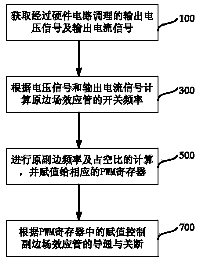
[0017] See figure 1 As shown, a specific embodiment of a synchronous rectification method for an LLC converter of the present invention includes:

[0018] Step 100, the digital signal processor acquires the output voltage signal and the output current signal conditioned by the hardware circuit;

[0019] The receiving output voltage detection circuit 20 and the output current detection circuit 30 can be analog-to-digital converters; in order to ensure that the digital signal processor can quickly respond to changes in load, it is required to receive the sampling frequency of the output voltage detection circuit 20 and the output current detection circuit 30 Cannot be undersampled.

[0020] In step 300, the digital signal processor 10 calculates the switching frequency of the original side field effect transistor according to the above-mentioned outpu...


PUM


Abstract

Disclosed are LLC (logical link control) converter synchronous rectification method and device. The method includes: acquiring an output voltage signal and an output current signal of a converter; calculating switching frequency of a primary side field-effect transistor according to the output voltage signal and the output current signal; judging operating statuses of the converter according to resonant frequency of the converter, and calculating different primary- and auxiliary-side frequencies and duty ratios according to the different operating statuses; controlling on and off of the primary- and auxiliary-side field-effect transistors to allow output synchronous rectification drive signals to open in the discontinuous operating status of the converter and shut down in the continuous operating status of the converter. By the use of the LLC converter synchronous rectification method and device, excessive loss due to non-zero open or shutdown current is reduced when synchronous rectifier tubes operate, and system efficiency is improved.

Description

technical field [0001] This patent relates to a software-controlled synchronous rectification method, in particular to a synchronous rectification control method using an LLC (Logical Link Control, Logical Link Control) resonant topology converter. Background technique [0002] With the continuous improvement of system performance, higher requirements are put forward for the efficiency, size and performance of the power supply. A properly designed LLC converter can basically realize that the primary side MOSFET always works in the ZVS open state under a full range of loads, which improves the system efficiency. At the same time, the introduction of secondary-side synchronous rectification technology also greatly reduces the on-state loss on the secondary rectification side of the system, making the LLC synchronous rectification topology more and more widely used in the medium and high power field. [0003] At present, LLC synchronous rectification control is mostly complete...

Claims


Application Information

Patent Timeline
Patent Type & Authority Patents(China)
IPC IPC(8): H02M3/335H02M7/217
Inventor 万仁春刘钧吴文江
Owner SHENZHEN VMAX NEW ENERGY CO LTD
Learn More