Outer convex inner arbitrary gear difference cam rolling moving transmission internal-combustion engine

A technology of internal combustion engine and movable tooth transmission, which is applied in the direction of machines/engines, mechanical equipment, etc., and can solve problems such as large impact, large mechanical wear, and large unbalanced centrifugal force

Inactive Publication Date: 2013-04-10
SICHUAN UNIV
View PDF5 Cites 11 Cited by
  • Summary
  • Abstract
  • Description
  • Claims
  • Application Information

AI Technical Summary

Problems solved by technology

Since this kind of internal combustion engine drives the crankshaft to rotate by the linear motion of the piston and the plane motion of the connecting rod, there is a large friction between the motion pairs, resulting in low transmission efficiency of the internal combustion engine.
The crankshaft connecting rod type internal combustion engine also has the following major defects: large volume; large unbalanced centrifugal force on the connecting rod and crankshaft; large impact and large vibration; and thus cause large mechanical wear and shorten the life of the internal combustion engine; complex structure, Processing, manufacturing, and assembly are difficult; in addition, the internal combustion engine and the transmission device are usually two independent machines, and the internal combustion engine needs to be additionally equipped with a reducer for subsequent transmission, resulting in a large volume

Method used


Image

  • Outer convex inner arbitrary gear difference cam rolling moving transmission internal-combustion engine
  • Outer convex inner arbitrary gear difference cam rolling moving transmission internal-combustion engine
  • Outer convex inner arbitrary gear difference cam rolling moving transmission internal-combustion engine

Examples


Embodiment Construction

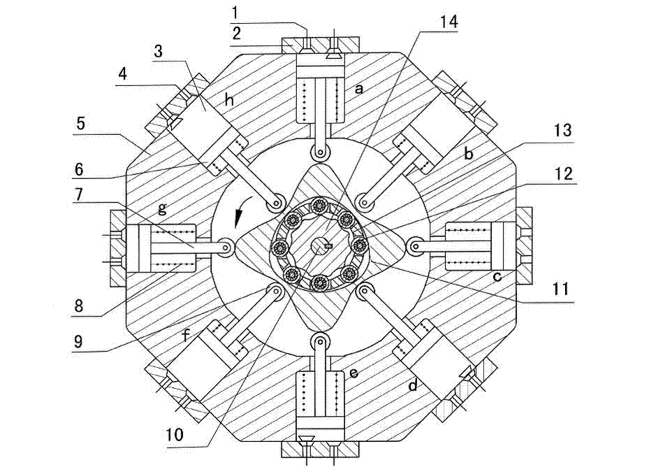
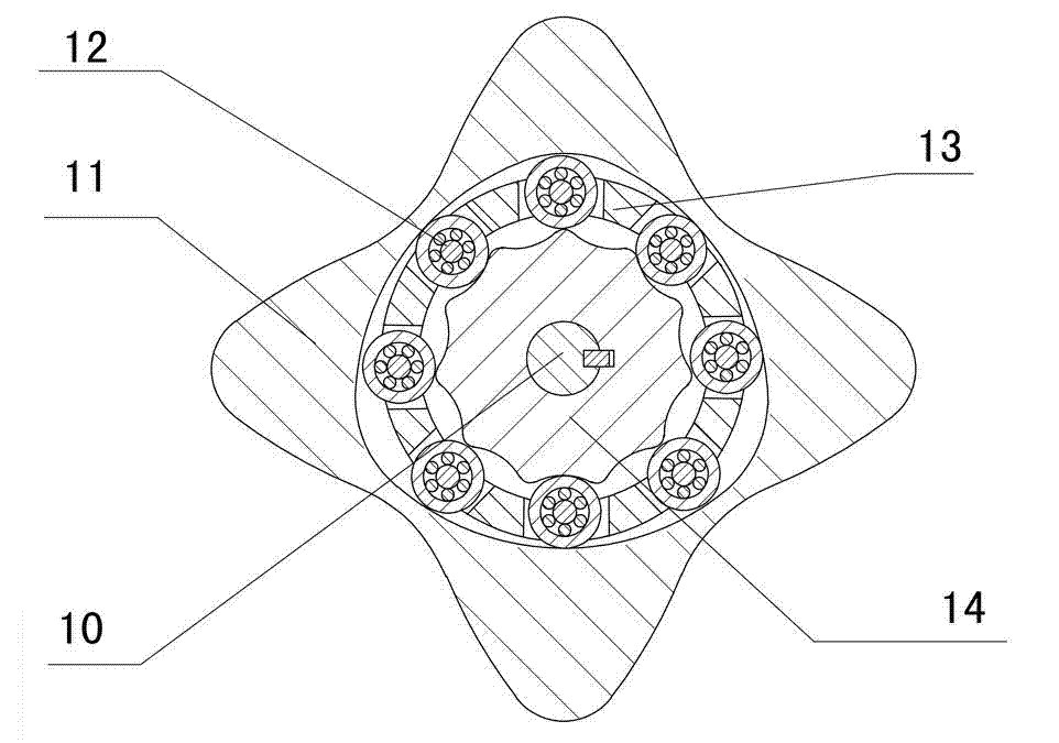
[0041] Figure 1~Figure 5 The cam rolling transmission internal combustion engine with any tooth difference inside the outer convex shown is composed of exhaust valve (1), cylinder head (2), cylinder (3), intake valve (4), cylinder block (5), piston (6) , push rod (7), spring (8), roller (9), output shaft (10), convex inner multi-phase inner cam (11), rolling movable tooth (12), movable gear rack (13), Center wheel (14) etc. are formed. Eight air cylinders (3) are evenly and symmetrically distributed in a circular shape around the outer convex inner multiphase inner cam (11), and the angle between two adjacent air cylinders is 45°. There is a piston (6) in each cylinder (3), one end of the push rod (7) is solidified with the piston (6), and the other end is equipped with a roller (9), and the push rod (7) is connected with the outer convex inner The multi-phase inner cams (11) change from sliding friction connection to rolling friction connection through rollers (9). One end...


PUM


Abstract

The invention discloses an outer convex inner arbitrary gear difference cam rolling moving transmission internal-combustion engine, relating to the field of fuel gas power and belonging to a multi-cylinder internal-combustion engine. The invention provides a novel internal-combustion engine; eight cylinders are distributed on the periphery of an outer convex inner multiphase inner cam symmetrically in a ring shape, so that a resultant force of the outer convex inner multiphase inner cam is zero; each cylinder piston directly acts on the outer convex inner multiphase inner cam through a push rod; and power is transmitted to an output shaft connected with a central wheel key by the outer convex inner multiphase inner cam through arbitrary gear difference inner cam rolling moving movable gear transmission. With the adoption of the internal-combustion engine, a connecting rod and a crank shaft in the traditional internal-combustion engine are saved; an outer convex multiphase inner cam rolling moving transmission mechanism has the characteristics of having no eccentric mass, and having an inertia force and working load self-balancing; the rotating speed of the output shaft depends on transmission ratio of movable gear transmission; when a movable gear frame is fixed, output by a central wheel is in low speed and large torque; and the internal-combustion engine can be widely applied to the fields of high-power engineering machinery and military and the like, such as excavators and armored cars. The internal-combustion engine is simple and compact in structure, small in axial size, self-balancing in stress, and stable in rotating.

Description

technical field [0001] The invention relates to the field of gas power, and more specifically relates to an internal combustion engine with a cam rolling transmission with an outer convex inner arbitrary tooth difference. Background technique [0002] The most commonly used internal combustion engine at present is a four-stroke crankshaft connecting rod type internal combustion engine. The transmission structure of this internal combustion engine all adopts a crank connecting rod mechanism, and the crankshaft is driven by the connecting rod, thereby converting the linear motion of the piston into the rotary motion of the crankshaft. Because this internal combustion engine drives the crankshaft to rotate by the linear motion of the piston and the planar motion of the connecting rod, there is a large friction between the kinematic pairs, resulting in low transmission efficiency of the internal combustion engine. The crankshaft connecting rod type internal combustion engine als...

Claims


Application Information

Patent Timeline
Patent Type & Authority Applications(China)
IPC IPC(8): F02B75/32F02B75/22
Inventor 梁尚明贺飞飞
Owner SICHUAN UNIV
Why Eureka
Try Eureka