Feature Size Shrinking Method

A feature size, semiconductor technology, applied in the direction of electrical components, semiconductor/solid-state device manufacturing, circuits, etc., can solve problems such as stripes, aggravate the edge of etched structure lines, damage, etc., to improve the roughness of line edges and improve the physical bombardment phenomenon , to avoid the effect of streak phenomenon

Active Publication Date: 2016-09-07
ADVANCED MICRO FAB EQUIP INC CHINA
View PDF4 Cites 0 Cited by
  • Summary
  • Abstract
  • Description
  • Claims
  • Application Information

AI Technical Summary

Problems solved by technology

like figure 1 As shown, due to the long chain C x f y The polymer is deposited unevenly on the surface of the semiconductor structure, which deforms the boundary shape of the circular or rectangular original patterned region 101a and becomes an irregular shape, which affects the patterned transfer quality
[0010] 2. Since the traditional plasma etching process is usually carried out in a low-pressure environment below 200mT, the relatively serious physical bombardment brought about during the deposition of macromolecular polymers further aggravates the damage to the edge of the etched structure line, causing more serious streak phenomenon
like figure 2 As shown, under the influence of the streak phenomenon, relatively serious burrs or streaks 102 appear on the boundary of the original patterned area 101b of the circular or rectangular design, which affects the pattern transfer accuracy on the one hand, and on the other hand, the appearance of burrs or streaks 102 , which also affects the etching quality of the patterned area 101b boundary

Method used


Image

  • Feature Size Shrinking Method
  • Feature Size Shrinking Method
  • Feature Size Shrinking Method

Examples


Embodiment Construction

[0040] In order to make the purpose, technical solution and advantages of the present invention clearer, the following will further describe the implementation of the present invention in detail in conjunction with the accompanying drawings.

[0041] Those skilled in the art can easily understand other advantages and effects of the present invention from the contents disclosed in this specification. The present invention can also be implemented or applied through other different specific implementation modes, and various modifications or changes can be made to the details in this specification based on different viewpoints and applications without departing from the spirit of the present invention.

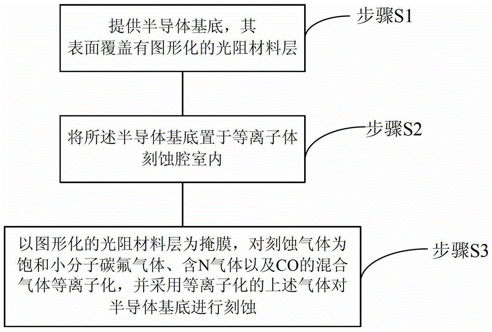
[0042] image 3 A flow chart of the steps of the feature size shrinking method provided by the present invention.

[0043] Such as image 3 As shown, the feature size shrinkage method provided in this specific embodiment includes the following steps:

[0044] Step S1 : providin...


PUM


Abstract

The invention relates to the technical field of semiconductors and discloses a critical dimension shrink method. According to the invention, CO is adopted to replace the traditional fluorocarbon compounds and H-containing fluorocarbon gases, and serves as a high molecular polymer gas in the critical dimension shrink method to support plasma etching under low-frequency radio-frequency power, so as to effectively control the molecular chain length and plasma energy and density in the critical dimension shrink process. The method can control the molecular chain lengths of polymers resulting from plasma etching and avoid the formation of long molecular chain polymers during the plasma etching process. Besides, the plasma etching process of the critical dimension shrink method is carried out under a high pressure environment, to further improve the phenomenon of physical bombardment of polymer deposition during the etching process, so as to effectively prevent the formation of stripes and improve the line edge roughness of the etched structure resulting from critical dimension shrink. The critical dimension shrink method can further improve the process quality and ensure the effective and high-quality shrink of critical dimension.

Description

technical field [0001] The invention relates to the technical field of semiconductors, in particular to the feature dimension shrinkage technology after photolithography under the next-generation semiconductor process node. Background technique [0002] With the continuous development of integrated circuit technology, semiconductor process nodes have gradually entered the era of 65nm and 45nm, and are moving towards more advanced 22nm and 16nm. However, as semiconductor process nodes continue to advance, the requirements for critical dimension (CD) in semiconductor device fabrication front-end process (FEOL) and back-end process (BEOL) become more and more stringent. Among them, the feature size of devices in the 65nm process has begun to be much smaller than the size of mainstream lithography. In the process of semiconductor device preparation, more and more semiconductor structures with feature sizes smaller than 65nm, or even smaller than 45nm and 28nm have begun to appea...

Claims


Application Information

Patent Timeline
Patent Type & Authority Patents(China)
IPC IPC(8): H01L21/3065H01L21/311
Inventor 王兆祥杜若昕刘志强苏兴才
Owner ADVANCED MICRO FAB EQUIP INC CHINA
Why Eureka
Try Eureka