
Multi-channel high speed data transmission system used for single event effect detection

A high-speed data transmission, single event effect technology, applied in transmission systems, electrical components, etc., can solve the problems of single event effect data reliability reduction, limited number of USB and serial ports, data transmission system crashes, etc., to achieve good consistency and versatility, fast monitoring, and the effect of simplifying the test operation process

Active Publication Date: 2013-04-10
BEIJING MXTRONICS CORP +1
View PDF3 Cites 7 Cited by
  • Summary
  • Abstract
  • Description
  • Claims
  • Application Information

AI Technical Summary

Problems solved by technology

[0003] At present, the data transmission system used in the single event effect detection test is mainly based on serial port and USB data line, which mainly has the following shortcomings: the number of data transmission is small, the speed is low, and the data transmission system is easy to be damaged when transmitting a large amount of high-speed data. Crash; Need to manually switch the channel of data transmission, which reduces work efficiency; Due to the limited number of USB and serial ports of the computer, data transmission of limited channels (1 to 5 channels) can only be completed at the same time; Serial and USB data transmission methods are used , the wiring in the vacuum tank is complicated and numerous, and one-to-one correspondence and marking are required during the wiring, which makes the preparation work before the test more cumbersome
All of these have greatly reduced the efficiency of single event effect detection and the reliability of data.

Method used


Image

  • Multi-channel high speed data transmission system used for single event effect detection
  • Multi-channel high speed data transmission system used for single event effect detection
  • Multi-channel high speed data transmission system used for single event effect detection

Examples


Embodiment Construction

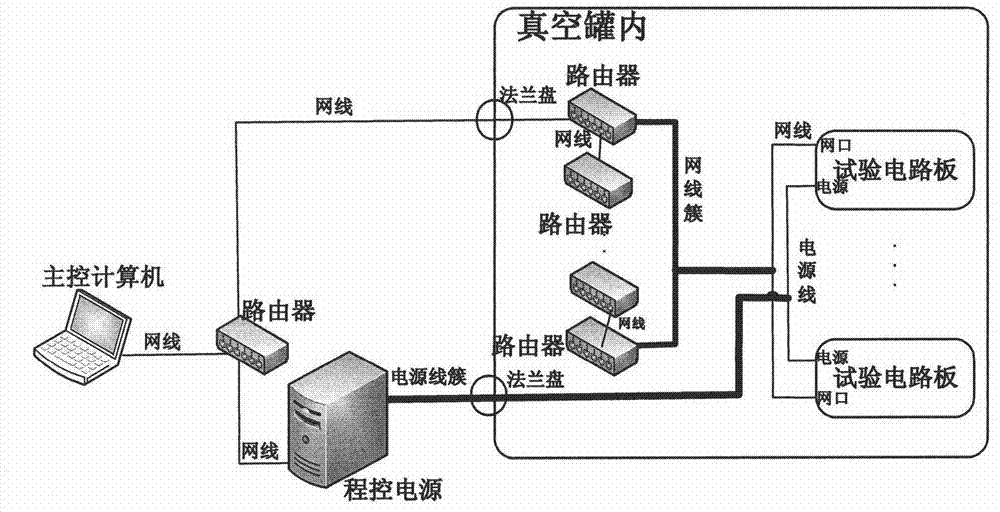
[0017] Such as figure 1 Shown is a schematic diagram of the composition of the transmission system of the present invention. The hardware system mainly includes the main control computer, router, program-controlled power supply outside the irradiation environment, and the test circuit board inside the irradiation environment. Among them, both the test circuit board and the program-controlled power supply are connected to the main control computer through a router, and the main control computer can control the program-controlled power supply to provide working voltage and power on and off for the irradiated circuit board. Multiple routers are connected in series to form multiple high-speed data transmission channels, which can communicate with the irradiated test circuit board through TCP / IP protocol to achieve high-speed data transmission.

[0018] The key of the present invention is to test the circuit board. The basic functional block diagram of the test circuit board is as fol...


PUM


Abstract

A multi-channel high speed data transmission system used for single event effect detection comprises a main control computer, routers, a programmable power supply, and a breadboard, wherein the main control computer, the routers and the programmable power supply are outside an irradiation environment, and the breadboard is inside the irradiation environment. The main control computer is connected with the programmable power supply and the breadboard through the routers, and the main control computer controls the programmable power supply to provide working voltage and power supply on-off for an irradiated circuit board. The multiple routers are connected to form multiple high speed data transmission channels, and high speed transmission of data can be achieved through communication of transmission control protocol (TCP) / internet protocol (IP) and the irradiated breadboard. The breadboard comprises an internet access chip, a programmable logic device, and an irradiated circuit, and the programmable logic device is transplanted with a UC / OS operating system with a TCP / IP protocol stack. The breadboard has internet access communication ability, and transmits data and communicates with the main control computer through a network cable. The system can complete communication with multiple tested devices in a single-particle test.

Description

Technical field [0001] The invention relates to a data transmission system. Background technique [0002] With the rapid development of integrated circuit reinforcement technology and technology, the operating frequency of aerospace devices has become higher and higher. At the same time, many aerospace devices need to undergo certain verification tests before being applied. Due to various factors, the radiation-resistant hardened devices can only be subjected to ground simulation tests to verify their anti-radiation hardening capabilities. In the verification test, the device under test needs to be configured in a typical working state. Therefore, for high-frequency devices, detecting data changes at the output end is a problem that needs to be solved urgently. With the development of aerospace technology, there are more and more applications of anti-radiation hardening devices, which makes the question of how to efficiently complete the radiation verification test become a prob...

Claims


Application Information

Patent Timeline
IPC IPC(8): H04L29/10H04L29/12
Inventor 董攀陈莉明范隆郑宏超岳素格马建华陈茂鑫文圣泉杜守刚王煌伟毕潇
Owner BEIJING MXTRONICS CORP
Learn More