

Electrolytic reduction system and method
The technology of an electrolytic cell and a flowing electrolytic cell, which is applied in the field of electrochemistry, can solve the problems of unsatisfactory industrial production, high energy consumption of electrodeposition equipment, and small electrodeposition area, so as to achieve a scientific electrolytic reduction method, reduce the cost of electrolytic deposition, The simple effect of the system
- Summary
- Abstract
- Description
- Claims
- Application Information
AI Technical Summary
Problems solved by technology
Method used
Image

Examples
Embodiment 1
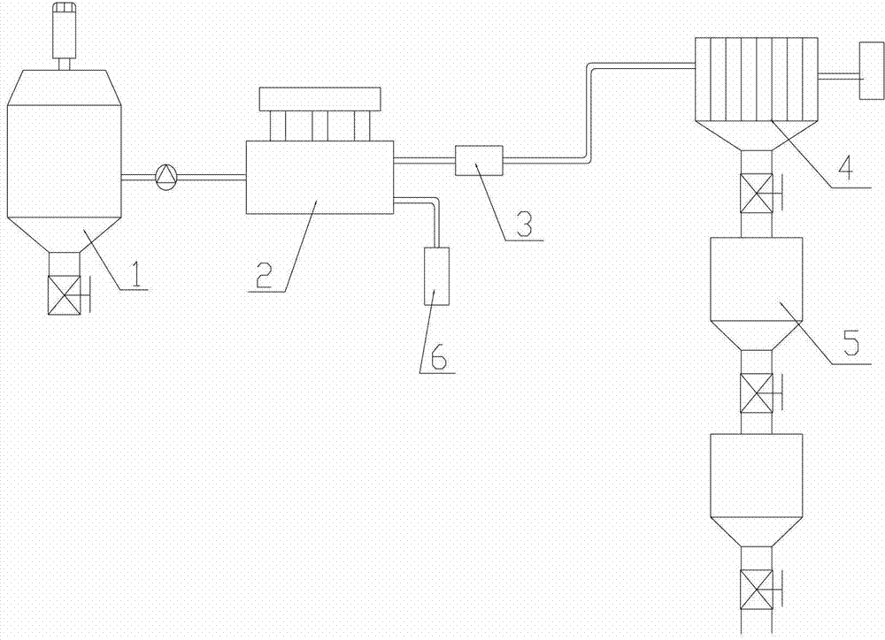
[0049] figure 1 It is a schematic structural diagram of the electrolytic reduction system disclosed in Example 1.
[0050] This embodiment discloses an electrolytic reduction system, such as figure 1 As shown, the electrolytic reduction system includes a control device, a dissolution tank 1, a solid-liquid separation device 2, a concentration monitor 3, a flow electrolytic cell 4 and a collection tank 5,
[0051] The dissolving tank 1 is provided with a dissolving tank inlet and a dissolving tank liquid outlet, and a heating mechanism (such as a jacket) and a stirring mechanism for accelerating the dissolution of metal or metal compound are also arranged in the dissolving tank 1 .
[0052] The solid-liquid separation device 2 adopts conventional solid-liquid separation equipment, such as filtration separation equipment, and the solid-liquid separation device 2 is provided with a solid-liquid separation device inlet, a solid-liquid separation device liquid outlet and a solid-l...
Embodiment 2
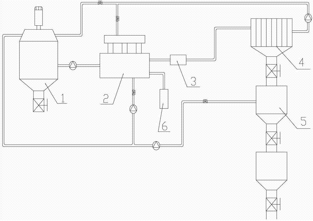
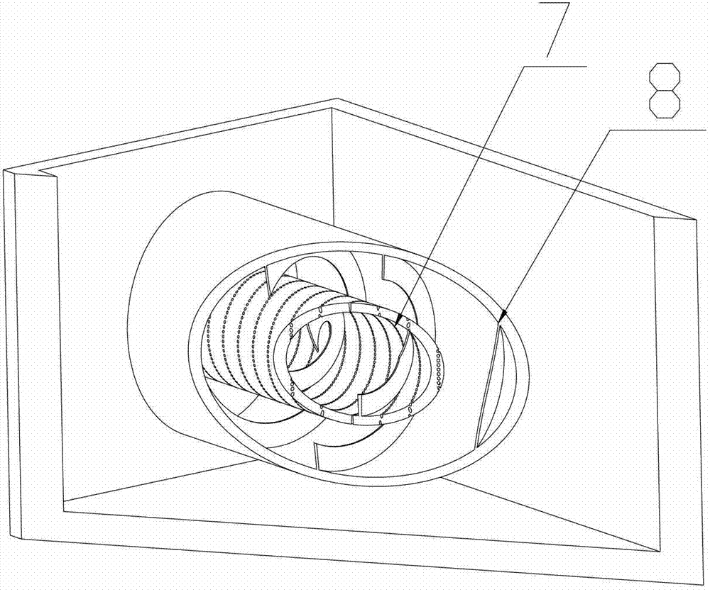
[0059] figure 2 It is a schematic structural diagram of the electrolytic reduction system disclosed in Example 2; image 3 It is a structural schematic diagram of the centrifugal separator of the present invention.
[0060] This embodiment discloses an electrolytic reduction system, such as figure 2 As shown, it includes a control device, a dissolution tank 1, a solid-liquid separation device 2, a concentration monitor 3, a flow electrolyzer 4 and a collection tank 5,
[0061] The dissolving tank 1 is provided with a dissolving tank inlet and a dissolving tank liquid outlet, and the inside or outside of the dissolving tank 1 is also provided with a heating mechanism and a stirring mechanism for accelerating the dissolution of metal or metal compound. The heating mechanism is a heating jacket arranged on the periphery of the dissolution tank 1, and heat transfer oil is arranged in the heating jacket, and the heat transfer oil is heated by electric heating to heat the soluti...
Embodiment 3
[0074] This embodiment provides an electrolytic reduction method, using the electrolytic reduction system described in Embodiment 1, comprising the following steps:
[0075] (1) Mix the solute metal or metal compound with the solvent in the dissolving tank, and the metal or metal compound reacts with the solvent to form a solution (electrolyte) containing metal ions; the heating mechanism heats the solution in the dissolving tank to 500°C and stirs Mechanism speed 30 rpm. In this embodiment, the solute is zinc oxide, and the solvent is potassium hydroxide.
[0076] (2) In the solid-liquid separation device, unreacted zinc oxide or other solid impurities in the solution are separated from the solution.
[0077] (3) Use a concentration monitor to detect the concentration of zinc ions in the solution, and adjust the voltage between the anode plate and the cathode plate in the electrolytic cell. Usually, the voltage between the anode plate and the cathode plate in the flow-type e...
PUM
 Abstract
Description
Claims
Application Information