An automatic control method for fire protection and idealized combustion in a furnace

An automatic control device and technology for fire prevention, applied in the field of idealized combustion automatic control and furnace fire prevention, can solve the problems of uneven air distribution and lack of oxygen, inconspicuous phenomena, and changes in boiler combustion state.

Active Publication Date: 2015-09-09
刘建松
View PDF7 Cites 0 Cited by
  • Summary
  • Abstract
  • Description
  • Claims
  • Application Information

AI Technical Summary

Problems solved by technology

[0002] When the coal combustion and air distribution of the furnace are artificially and automatically adjusted, a local high temperature condition inside the furnace is formed, resulting in an increase in NOx generated by combustion, forming a local high temperature and uneven air distribution and lack of oxygen, resulting in high temperature sulfur corrosion of the water wall; the actual operation of the boiler The working condition often deviates from the design working condition, whether it is the change of the volatile content of the fuel mixture, the change of the initial temperature, the change of the fuel calorific value, the change of the concentration of the imported fuel mixture, the change of the activation energy of the fuel mixture, and the change of the air distribution volume of the burner, all of which will cause the furnace combustion. When the change of the type of coal used leads to the change of the combustion state of the boiler, the phenomenon of flameout is prone to occur under low load
[0003] At present, there is no feasible control method at home and abroad to realize the automatic control of boiler furnace fire prevention and idealized combustion. The coal quality is stable, and the change of the combustion state of the boiler due to the change of the coal quality is not obvious, so the international development of this field has not been carried out. At present, there is no method to realize the automatic control of furnace fire prevention and ideal combustion at home and abroad.

Method used


Image

  • An automatic control method for fire protection and idealized combustion in a furnace
  • An automatic control method for fire protection and idealized combustion in a furnace
  • An automatic control method for fire protection and idealized combustion in a furnace

Examples


Embodiment 1

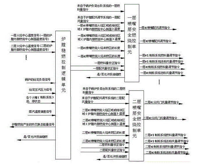
[0136] Precise full furnace control unit with direct regulation:

[0137] Such as figure 1 Shown: The signals input to the control unit of the whole furnace include: the flame center temperature signal of each layer or the side temperature signal of the combustion center inside the furnace of each layer, the boiler given load signal, the given main steam pressure signal, each burner (pulverizing System) start and stop status signal, boiler fuel volume command signal output by the boiler load regulation system, the whole furnace control unit firstly controls the boiler given load signal, given main steam pressure signal and burner (pulverizing system) start and stop The state signal is calculated to calculate the given value of the flame center temperature of each burner layer:

[0138] ,

[0139] T nSV The principle of value selection is: T of each layer nSV The value is close, 900℃nSV <1500℃

[0140] The calculated given value of the flame center temperature of each no...

Embodiment 2

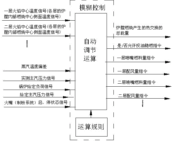
[0142] Directly regulated, precise, steam temperature deviation corrected, load deviation corrected full furnace control unit:

[0143] Such as figure 2 Shown: The signals input to the control unit of the whole furnace include: the flame center temperature signal of each layer or the combustion center side temperature signal inside the furnace of each layer, the boiler given load signal, the steam temperature deviation signal, the given main steam pressure signal, the measured The main steam pressure signal, each burner (powder making system) start and stop status signal; inside the whole furnace control unit, the boiler load given signal, the given main steam pressure signal and the burner (powder making system) start and stop status are first The signal is calculated to calculate the given value of the flame center temperature of each burner layer:

[0144] ,

[0145] T nSV The principle of value selection is: T of each layer nSV The value is close, 900℃nSV <1500℃

...

Embodiment 3

[0148] Full furnace control unit in corrected form:

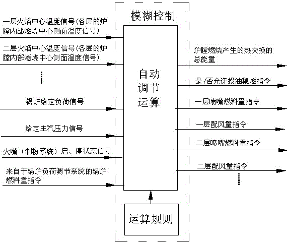
[0149] Such as image 3 Shown: The signals input to the control unit of the whole furnace include: the flame center temperature signal of each layer or the side temperature signal of the combustion center inside the furnace of each layer, the boiler given load signal, and the start and stop status signals of each burner (pulverizing system) ;In the control unit of the whole furnace, firstly calculate the given load signal of the boiler, the given main steam pressure signal and the start and stop state signals of the burner (pulverizing system), and calculate the given value of the flame center temperature of each burner layer:

[0150] ,

[0151] T nSV The principle of value selection is: T of each layer nSV The value is close, 900℃nSV <1500℃

[0152] The calculated given value of the flame center temperature of each burner layer and other input signals are used for automatic control calculation, and the automatic con...


PUM


Abstract

The invention discloses an automatic control method for preventing extinguishment and realizing ideal combustion for a hearth. The automatic control method is implemented by the aid of a full hearth control unit, signals inputted into the full hearth control unit at least include center temperature signals of various flame layers, given load signals of a boiler and starting and stopping state signals of various nozzles or pulverizing systems, automatic control operation is carried out inside the full hearth control unit, and signals outputted after automatic control operation at least include one type of fuel quantity instructions or fuel quantity correcting instructions of the various layers, air distribution quantity instructions or air distribution quantity correcting instructions of the various layers, oil feed combustion stabilizing instructions and total heat exchange energy signals generated during combustion of the hearth. The automatic control method has the advantages that the fuel coal quantity of the boiler and air quantities of the combustion nozzles can be adjusted automatically, excessively high temperature of the inside of the hearth is prevented, the boiler keeps in a stable combustion state, the extinguishment condition is stopped, the automatic control method is safe and convenient, and accordingly purposes of preventing extinguishment and realizing ideal low-nitrogen combustion are achieved for the hearth.

Description

technical field [0001] The invention relates to a method for controlling safe combustion of a furnace hearth of a boiler, in particular to an automatic control method for fire prevention and idealized combustion of a furnace hearth of a boiler. Background technique [0002] When the coal combustion and air distribution of the furnace are artificially and automatically adjusted, a local high temperature condition inside the furnace is formed, resulting in an increase in NOx generated by combustion, forming a local high temperature and uneven air distribution and lack of oxygen, resulting in high temperature sulfur corrosion of the water wall; the actual operation of the boiler The working condition often deviates from the design working condition, whether it is the change of the volatile content of the fuel mixture, the change of the initial temperature, the change of the fuel calorific value, the change of the concentration of the imported fuel mixture, the change of the acti...

Claims


Application Information

Patent Timeline
Patent Type & Authority Patents(China)
IPC IPC(8): F23N5/00
Inventor 刘建松李福胜王鑫磊
Owner 刘建松
Why Eureka
Try Eureka