Superconducting coil, superconducting energy storage device and control method

A technology of superconducting coils and superconducting wires, which is applied in the directions of superconducting magnets/coils, superconducting/high-conducting conductors, superconducting elements, etc., and can solve problems such as large internal friction of coils, low current conduction density, and low energy density

Inactive Publication Date: 2013-04-17
UNIV OF ELECTRONICS SCI & TECH OF CHINA
View PDF4 Cites 4 Cited by
  • Summary
  • Abstract
  • Description
  • Claims
  • Application Information

AI Technical Summary

Problems solved by technology

[0002] Since the inductance coil wound with traditional copper wire has high internal resistance and low current conduction density, resulting in large internal friction and low energy density of the coil, it is impossible to use the traditional wire coil technology to prepare electromagnetic storage devices with general practical application significance. Energy coil and electromagnetic energy storage device
The use of superconducting coils to prepare superconducting electromagnetic energy storage devices has significant advantages of low loss and high current density, but in practical applications, it is necessary to solve the problem of effective cooling of superconducting coils, superconducting coil design problems, and superconducting coil-based Current Sensitivity Safeguard Operation Issues

Method used


Image

  • Superconducting coil, superconducting energy storage device and control method
  • Superconducting coil, superconducting energy storage device and control method
  • Superconducting coil, superconducting energy storage device and control method

Examples


Embodiment 1

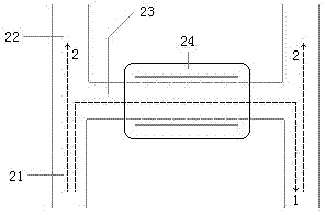
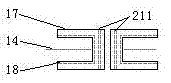
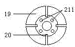
[0053] Embodiment one: if figure 1 As shown, a superconducting coil includes a superconducting coil body, a coil frame 17, and a composite superconducting switch. The superconducting coil body is wound from a superconducting initial strip or a high-current composite superconducting wire. The composite superconducting switch includes a superconducting coil body end wire 21, a superconducting current lead wire 22, a superconducting switch lead wire 23, and a superconducting switch 24, and the two ports of the superconducting coil body end wire 21 are respectively connected to the two ports of the superconducting current lead wire 22 , the superconducting switch lead wire 23 is connected across the connection between the superconducting coil body end wire 21 and the superconducting current lead wire 22 , and the superconducting switch 24 is connected to the two ports of the superconducting coil body end wire 21 through the superconducting switch lead wire 23 .

Embodiment 2

[0054] Embodiment 2: On the basis of Embodiment 1, the superconducting coil body, the superconducting coil body end wire 21, the superconducting current lead 22, and the superconducting switch lead 23 are YBa 2 Cu 3 o 7-x High temperature superconducting coated wire, the YBa 2 Cu 3 o 7-x Superconducting wire is T c ~90K.

Embodiment 3

[0055] Embodiment 3: On the basis of Embodiment 1, the superconducting coil body, the superconducting coil body end wire 21, the superconducting current lead 22, and the superconducting switch lead 23 are Bi 2 Sr 2 Ca 2 Cu 3 o 10+x multi-core wire.


PUM


Abstract

The invention relates to the field of electromagnetic energy storage and control, in particular to a superconducting coil, a superconducting energy storage device and a control method. Aiming at problems in the prior art, the superconducting coil provided with an auxiliary cooling structure and a hybrid superconducting wire forms an electromagnetic energy storage device, and working states of an energy storage device are subjected to automatic selection according to load changes by the energy storage control device and the control method to realize digital control on the working states of the energy storage device so as to realize efficient and reliable control with a protective function. A superconducting wire coil body, a coil framework, a composite superconducting switch and the like form the superconducting coil to form a superconducting device, and the design is completed by the control method for the superconducting device. The superconducting coil, the superconducting energy storage device and the control method are applied to the field of electromagnetic energy storage and control.

Description

technical field [0001] The invention relates to the field of electromagnetic energy storage and control, in particular to a superconducting coil, a superconducting energy storage device and a control method. Background technique [0002] Since the inductance coil wound with traditional copper wire has high internal resistance and low current conduction density, resulting in large internal friction and low energy density of the coil, it is impossible to use the traditional wire coil technology to prepare electromagnetic storage devices with general practical application significance. Energy coil and electromagnetic energy storage device 。 The use of superconducting coils to prepare superconducting electromagnetic energy storage devices has significant advantages of low loss and high current density, but in practical applications, it is necessary to solve the problem of effective cooling of superconducting coils, superconducting coil design problems, and superconducting coil-b...

Claims


Application Information

Patent Timeline
Patent Type & Authority Applications(China)
IPC IPC(8): H01F6/06H01B12/00H01F6/04H02J15/00H02H7/00G06F17/50
CPCY02E40/60
Inventor 金建勋
Owner UNIV OF ELECTRONICS SCI & TECH OF CHINA
Why Eureka
Try Eureka