Power inductor and manufacturing method thereof

A technology of a power inductor and a manufacturing method, which is applied to the field of power inductors and their manufacturing, can solve the problems of occupying powder space, high cost of electrodes, and reduction of powder materials, so as to reduce labor costs, high temperature characteristics, and cost control improvement and reduction. The effect of material cost

Inactive Publication Date: 2013-04-17
王向群
View PDF5 Cites 19 Cited by
  • Summary
  • Abstract
  • Description
  • Claims
  • Application Information

AI Technical Summary

Problems solved by technology

Due to the increasingly stringent control of electromagnetic radiation, cross-interference and electromagnetic pollution brought about by environmental changes (EMC control standards), inductors play an important role in absorbing surges in the circuit, and the current resistance characteristics of power inductors , EMI characteristics can not meet the requirements of the market
Most of the small-sized chip power inductors in the current market are not integrally formed. There are practical difficulties such as low inductance, high current resistance, poor reliability, high temperature, and poor EMI characteristics. At the same time, the degree of automation is not high. , its high labor cost is also an obstacle to the development of the industry
[0003] At present, there are power inductor electrodes integrally formed by powder die-casting in the industry. The process adopted is to embed the end of the electrode into the inside of the powder for fixing.

Method used


Image

  • Power inductor and manufacturing method thereof
  • Power inductor and manufacturing method thereof
  • Power inductor and manufacturing method thereof

Examples


Embodiment Construction

[0030] In order to have a clearer understanding of the technical features, purposes and effects of the present invention, the specific implementation manners of the present invention will now be described in detail with reference to the accompanying drawings.

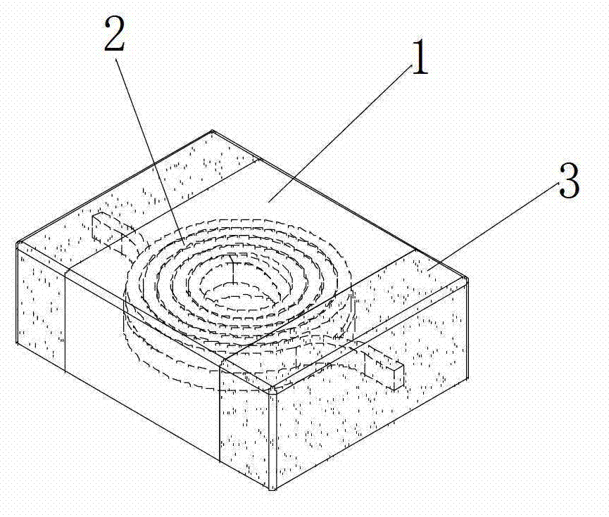
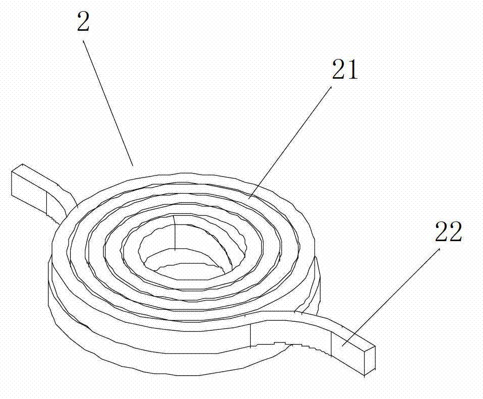
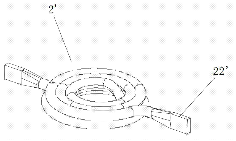
[0031] like figure 1 and figure 2 As shown, the power inductor of the present invention includes an inner core 2 and a die-cast body 1 tightly covering the inner core 2 . The inner core 2 is a coil structure wound by an enameled wire, and includes a main body 21 and an extension 22 extending from the main body 21 . The extension 22 is flat. The die-casting body 1 is formed by integrally die-casting the inner core 2 with magnetic metal powder. The die-casting body 1 seals the inner core 2 therein with high density, and the extension part 22 exposes the opposite end surface of the die-casting body 1 .

[0032] The enameled wire adopts high-strength hot-melt (high temperature resistant) enameled wire, which can be flat ...


PUM

PropertyMeasurementUnit
Granularityaaaaaaaaaa

Abstract

The invention discloses a power inductor and a manufacturing method thereof. The power inductor comprises an inner core and a die-casting body closely coating the inner core, the inner core is of a coil structure wound by an enameled wire and comprises a body and extension portions extending out of the body, the die-casting body is formed by integrally diecasting magnetic metal powder on the inner core, the extension portions expose out of the opposite end faces of the die-casting body, and metal layers are coated on the surfaces of the ends, corresponding to the extension portions, of the die-casting body to coat the ends of the die-casting body so as to form electrodes of the power inductor. By integral die-casing forming of the magnetic metal powder and the inner core, automatic large production can be achieved, and material cost and labor cost are reduced greatly. Besides, a traditional welding process of a coil and electrodes is cancelled, potential quality hazards due to the fact that various problems of welding spots and the like are prone to occur in the traditional process are overcome completely, and insulation property, magnetic shielding property, current resisting property, high-temperature property and cost control of finished products are improved greatly.

Description

technical field [0001] The invention relates to an inductor and a manufacturing method thereof, in particular to a power inductor and a manufacturing method thereof. Background technique [0002] With the rapid development of science and technology, the size of various mobile digital products including mobile phones is getting smaller and smaller. Due to the increasingly stringent control of electromagnetic radiation, cross-interference and electromagnetic pollution brought about by environmental changes (EMC control standards), inductors play an important role in absorbing surges in the circuit, and the current resistance characteristics of power inductors , EMI characteristics can not meet the requirements of the market. Most of the small-sized chip power inductors in the current market are not integrally formed. There are practical difficulties such as low inductance, high current resistance, poor reliability, high temperature, and poor EMI characteristics. At the same t...

Claims


Application Information

Patent Timeline
IPC IPC(8): H01F17/04H01F27/29H01F41/00
Inventor 王向群
Owner 王向群
Why Eureka
Try Eureka