Upper part seal structure of aluminium electrolytic tank

A technology of sealing structure and aluminum electrolytic cell, which is applied in the field of upper sealing structure of aluminum electrolytic cell, can solve problems such as increase of horizontal current in aluminum liquid layer, decrease of current efficiency, thickening of surrounding furnace side, etc., so as to improve work efficiency and heat preservation performance, the effect of reducing the amount of diffusion

Active Publication Date: 2015-06-03
CENT SOUTH UNIV
View PDF3 Cites 0 Cited by
  • Summary
  • Abstract
  • Description
  • Claims
  • Application Information

AI Technical Summary

Problems solved by technology

Especially when the pole change occurs at the four corners of the electrolytic cell, it will cause the surrounding furnace sides to become thicker and the outstretched legs to become longer
Extending the legs will lead to an increase in the horizontal current of the aluminum liquid layer and a decrease in current efficiency

Method used


Image

  • Upper part seal structure of aluminium electrolytic tank
  • Upper part seal structure of aluminium electrolytic tank

Examples


Embodiment Construction

[0021] Below in conjunction with accompanying drawing, the specific implementation manner of this patent is described in further detail.

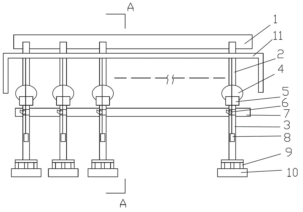
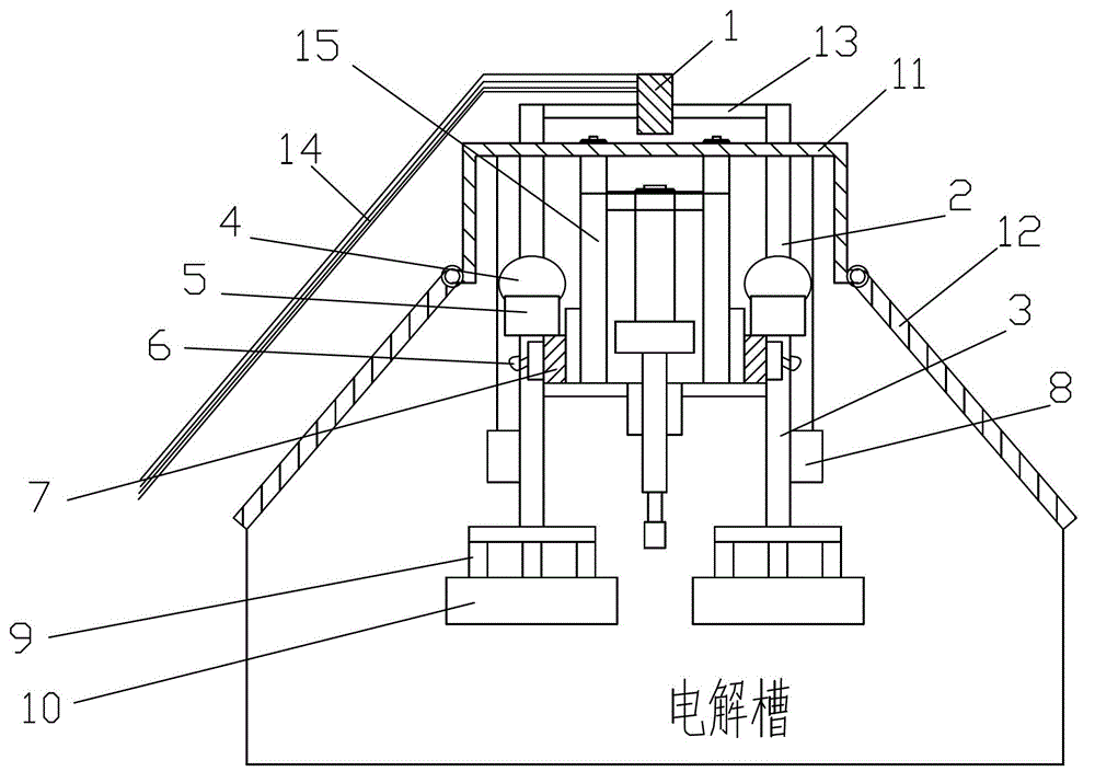
[0022] Such as Figures 1 to 2 As shown, an upper sealing structure of an aluminum electrolytic cell, the outer cover 11 is a steel outer cover, the outer cover 11 is installed on the door-shaped column 15 of the load-bearing truss of the electrolytic cell and is arranged on the upper side of the electrolytic cell, and the two sides of the outer cover 11 are covered by the tank The plate 12 is closed, and the upper side of the tank cover plate 12 is hinged on the outer cover 11, and the tank cover plate 12 is controlled to rotate by the rotating device. When the tank cover plate 12 is closed, the lower side of the tank cover plate 12 contacts and seals with the upper part of the edge of the electrolytic cell. When the tank cover plate 12 is opened, it can be automatically opened by a rotating device, so as to facilitate the replacement of t...


PUM


Abstract

The invention discloses an upper part seal structure of an aluminium electrolytic tank. The seal structure comprises an anode guide rod, a beam bus and a vertical column bus. An anode carbon block is arranged at the end of the anode guide rod. An outer cover is arranged above the electrolytic tank. The outer cover is connected with a tank cover plate of the electrolytic tank, and an opening of the whole electrolytic tank is packed by a structure formed by the outer cover and the tank cover plate of the electrolytic tank. The device favorably improves the whole thermal insulation properties of the aluminium electrolytic tank, and also reduces the diffusing capacity of flue gas produced in the aluminium electrolytic tank around factories, so that the heat dissipation loss of the upper part of the aluminium electrolytic tank can be greatly reduced, heat balance when a low voltage is normally operated is maintained, and the thermal insulation requirement of a future low temperature aluminium electrolytic tank is met.

Description

technical field [0001] The invention relates to an upper sealing structure of an aluminum electrolytic cell. Background technique [0002] The development trend of contemporary aluminum electrolysis technology is to develop towards the technical direction of "low pole distance, high density, low power consumption and low emission". It is the current development trend of the aluminum industry at home and abroad to research and develop heat-insulating aluminum electrolytic cells, reduce the heat loss of electrolytic cells, and realize the stable and efficient operation of aluminum electrolytic cells at low voltage and high pole distance [1] . Since inert anodes have not been used in large-scale production, ordinary carbon anodes have not been replaced, and aluminum electrolytic cells must be periodically changed to maintain their normal operation [2] . When the aluminum electrolytic cell is in operation, gas is generated under the anode bottom palm, and the generated gas pa...

Claims


Application Information

Patent Timeline
Patent Type & Authority Patents(China)
IPC IPC(8): C25C3/08
Inventor 李贺松田应甫陈桢张思源李贺
Owner CENT SOUTH UNIV
Why Eureka
Try Eureka