

Lacing hole structure of turbine blade and loose lacing wire installation structure of the same turbine blade
A technology of steam turbine blades and tendon holes, which is applied in the direction of blade support components, mechanical equipment, engine components, etc., can solve the problems of low density of titanium alloy, low vibration deformation of blades, and small centrifugal force, etc., and achieve simple structural shape and reduce stress Level, enhance the effect of vibration damping ability
- Summary
- Abstract
- Description
- Claims
- Application Information
AI Technical Summary
Problems solved by technology
Method used
Image

Examples
Embodiment Construction
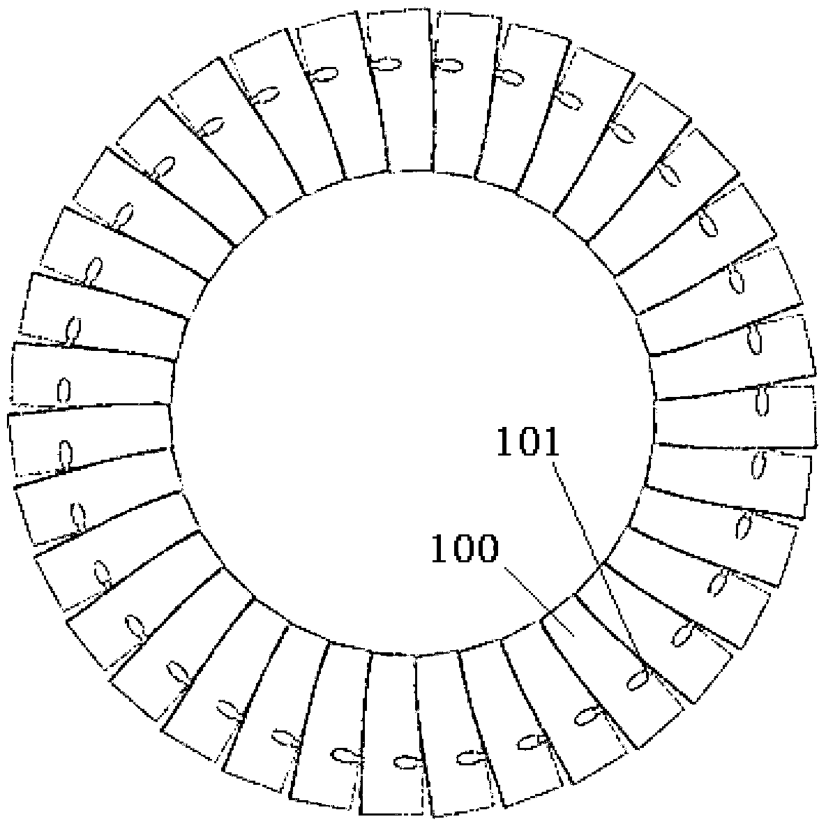
[0025] see figure 1 1. Tension holes are processed at about 65% to 80% of the blade height of the steam turbine moving blade 100, and the annular loose tension reinforcement 101 with a circular cross section passes through the blade tension holes to connect the blades to form a complete ring structure.
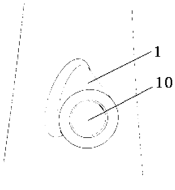
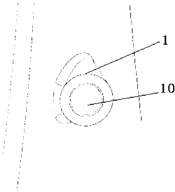
[0026] see Figure 2a to Figure 3d As shown, the present invention is processed with a straight circular ring-shaped boss structure 1 on the surface of the airfoil, and its axial direction is perpendicular to the normal direction of the airfoil cross section and parallel to the tangential direction of the impeller. The outer surface of the boss structure 1 is in line with the blade The intersection line between the pressure side and the suction side is transitioned with a rounded corner. The through hole in the middle of the boss structure 1 is the rib hole 10 of the blade. Its axis direction is consistent with the axis direction of the boss structure 1. In the actual processi...
PUM
| Property | Measurement | Unit |
|---|---|---|
| Length | aaaaa | aaaaa |
Abstract
Description
Claims
Application Information