
Two-stage incineration device and incineration system

An incineration device and incinerator technology, applied in the direction of incinerators, combustion methods, combustion types, etc., can solve the problems of inability to realize the recycling of phosphorus resources, affecting the heat transfer effect, and producing a large amount of industrial phosphorus-containing waste slag and liquid.

Active Publication Date: 2017-04-05
ZHEJIANG XINAN CHEM INDAL GROUP +1
View PDF5 Cites 0 Cited by
  • Summary
  • Abstract
  • Description
  • Claims
  • Application Information

AI Technical Summary

Problems solved by technology

And industrial phosphorus-containing waste residue and waste liquid, especially pesticide phosphorus-containing waste residue and waste liquid, such as the mother liquor produced in the glyphosate production process or the treated mother liquor contains sodium salt (or other alkali metal salts), the high-temperature smoke from incineration Gas makes the product in a molten state and is easily attached to the inner wall of the furnace tube. Severe fouling affects the heat transfer effect. At the same time, the combustion gun is easy to block during the incineration of saline waste liquid.
Existing incinerators cannot realize the recycling of phosphorus resources in these waste residues and waste liquids, and the production of industrial phosphorus-containing waste residues and waste liquids (including pesticide phosphorus-containing waste liquids) is large, and the processing capacity of existing incinerators is not enough to meet the demand for processing volume , and cannot meet the process requirements of solid continuous discharge

Method used


Image

  • Two-stage incineration device and incineration system
  • Two-stage incineration device and incineration system
  • Two-stage incineration device and incineration system

Examples


Embodiment

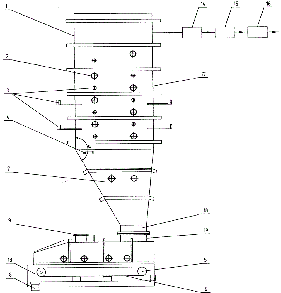
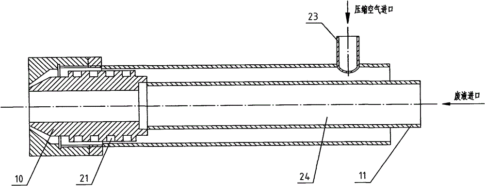
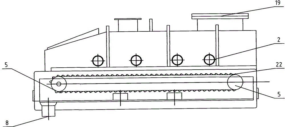
[0021] This equipment is connected by a vertical incinerator 1 and a horizontal incinerator 13 to form an L-shaped furnace body. The vertical incinerator 1 is composed of a square combustion zone 17 and a cone settlement zone 7. In the combustion zone 17, a layered spiral is adopted along the wall The waste atomization gun 2 and the fuel combustion gun 3 are arranged horizontally and vertically. The waste atomization gun 2 adopts a two-fluid design and is divided into a gun head 10, a gun body and a gun tail 11. The gun body is divided into two layers. There is a spiral groove 21 in the middle, the waste liquid and waste residue pass through the waste atomizing gun 2, the inner gun body 24 of the atomizing gun, the compressed air passes through the outer gun body of the atomizing gun, and enters the combustion zone 17 at the gun head, and the fuel and air pass through The fuel burner 3 enters the combustion zone, and the waste atomization gun 2 and the fuel burner 3 are arrange...


PUM


Abstract

The invention provides a main device for a phosphorus containing waste incineration disposal process. A two-part type incinerator forms an L-shaped furnace body by connecting a vertical furnace (1) and a horizontal furnace (13). The vertical furnace (1) is composed of a cuboid combustion area (17) and a cone depression area (7). Waste liquid atomization guns (2) and fuel combustion guns (3) are alternately arranged along the wall of the cuboid combustion area (17). Soot blowers (4) are arranged in the connection position of the cone depression area (7) and the cuboid combustion area (17) along the front side wall of the furnace from top to bottom. The fuel combustion guns (3) are arranged in the middle portion of the cone depression area (7). An exit (18) of the cone depression area (7) is communicated with a feed inlet (19) of the vertical furnace (13). The vertical furnace (13) utilizes a scale circulation type fire grate (6). A feed outlet is arranged at the front end of the fire grate. Combustion tail gas passes through an exit (20) which is formed in the top portion of the vertical furnace (1) and passes through a secondary combustion settling chamber (14), a heat exchanging unit (15) and a flue gas cleaning device (16) in sequence.

Description

technical field [0001] The invention belongs to an incineration treatment device for phosphorus-containing waste residue and waste liquid, in particular to an incineration treatment device for pesticide phosphorus-containing waste liquid. Background technique [0002] Due to the phosphorus-containing waste residues and waste liquids in many industries such as oil refining, chemical industry, medicine and pesticides, according to environmental protection requirements, the discharge of waste residues and waste liquids has strict requirements on phosphorus content, especially for the pesticide industry, phosphorus-containing waste liquids and waste residues are more common. Such as glyphosate, paraquat, acetochlor, acephate, chlorpyrifos, propanil, glufosinate, imidacloprid, chlorimsulfuron, triazophos, malathion and other pesticide industries, and their raw materials or Production of intermediates, such as phosphorus trichloride, phosphorus oxychloride, phosphorous acid, dimet...

Claims


Application Information

Patent Timeline
Patent Type & Authority Patents(China)
IPC IPC(8): F23G7/02F23G7/04
Inventor 王伟周曙光韩云涛詹波朱建民马清艳姜胜宝揭少卫佘慧玲祝小红华瑛
Owner ZHEJIANG XINAN CHEM INDAL GROUP
Learn More