Anti-scratching optical reflecting film and manufacturing method of the same
An optical reflection, anti-scratch technology, applied in optics, optical components, diffusing components, etc., can solve the problems of easily scratched light guide plate, folded or scratched reflective film, etc., to reduce scratches, uniform brightness, Significant scratch resistance
- Summary
- Abstract
- Description
- Claims
- Application Information
AI Technical Summary
Problems solved by technology
Method used
Image


Examples
preparation example Construction
[0038] The preparation method of the anti-scratch optical reflection film provided by the invention comprises the following steps:
[0039] (1) Prepare the coating solution: add adhesive, particles, UV absorber and solvent in sequence, and stir for 1-3 hours;
[0040] (2) Apply the coating solution obtained in step (1) evenly on the substrate, and bake at 80-120°C for 1-30 minutes.
[0041] Prepare anti-scratch optical reflective film according to above-mentioned method, the test method of each performance of gained reflective film is briefly described as follows:
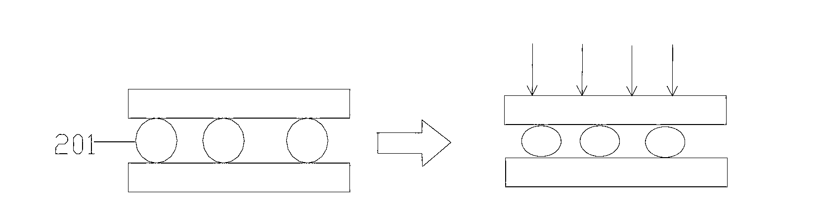
[0042] Degree of scratches: Put the reflective film into the backlight module, and then put it into the vibration test box for a 2-hour vibration test. After the vibration test is completed, take out the light guide plate and the reflective film, and observe the scratches on the light guide plate and the reflective film. Scratches on the contact side of the light guide plate.
[0043] Vibration experiment: Vibrat...
Embodiment 1
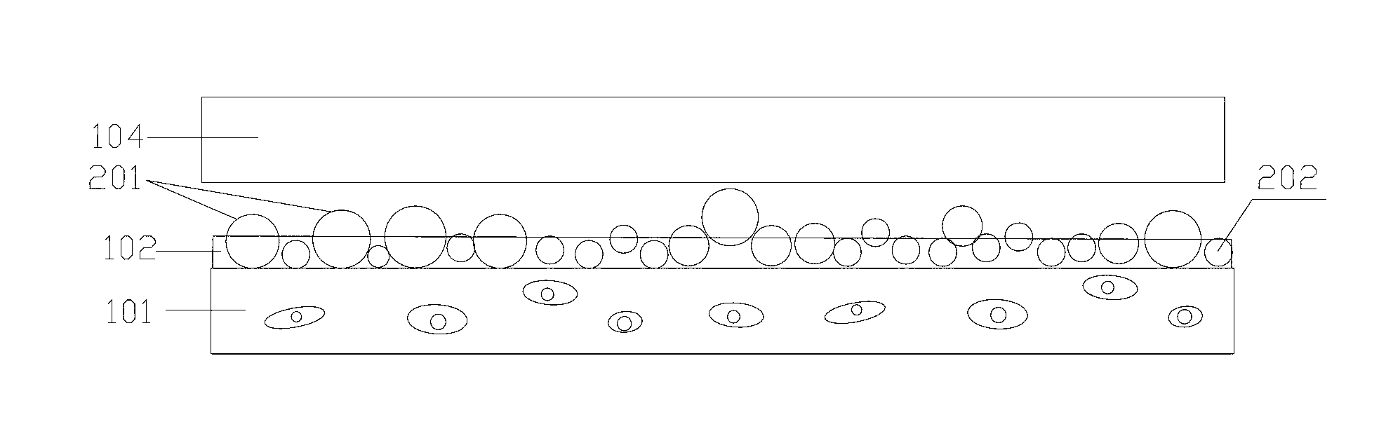
[0046] According to the method above, the anti-scratch optical reflection film is prepared. The substrate used is white PET with a thickness of 150 μm. The white PET is provided with a protective coating. The adhesive used for the coating is a polyurethane adhesive, and the adhesive is 100 parts by weight. , Particles are 35 parts by weight. The particles include silica particles accounting for 20% of the total weight of the particles, with a particle size of 5 μm; nylon particles accounting for 80% of the total weight of the particles, with a particle size of 10 μm. The thickness of the adhesive layer after drying was 8 μm.
Embodiment 2
[0048] Prepare anti-scratch optical reflective film according to the above method, the base material used is white PET, thickness is 188 μ m, is provided with protective coating on white PET, the adhesive used for coating is acrylate adhesive, and adhesive is 100 weight Parts, particles are 25 parts by weight. Particles include barium sulfate particles accounting for 10% of the total weight of the particles, and the particle size range is 3 μm; titanium dioxide particles accounting for 10% of the total particle weight, the particle size range is 1 μm; nylon particles accounting for 80% of the total particle weight, the particle size range The range is 10 μm. The thickness of the adhesive layer after drying is 6-8 μm.
PUM
| Property | Measurement | Unit |
|---|---|---|
| Particle size | aaaaa | aaaaa |
| Particle size | aaaaa | aaaaa |
| Thickness | aaaaa | aaaaa |
Abstract
Description
Claims
Application Information