Magnetizing apparatus on basis of flywheel energy storage

A flywheel energy storage and magnetizer technology, which is applied to magnetic objects, electromechanical devices, electromechanical converters, etc., can solve the problems of large space occupation, environmental friendliness, limited number of capacitor charging and discharging, and achieve space utilization and The electromagnetic efficiency is improved, the magnetic bearing control components at both ends of the radial direction are reduced, and the number of charge and discharge times is increased.

Active Publication Date: 2013-04-24
ZHEJIANG UNIV
View PDF6 Cites 6 Cited by
  • Summary
  • Abstract
  • Description
  • Claims
  • Application Information

AI Technical Summary

Problems solved by technology

[0005] The electromagnet type magnetizer can be made very large, and the magnetic field can be directly established without charging, but because the electromagnetic coil is fixed on the iron core, the workpiece to be magnetized is located outside the electromagnetic coil during operation, and its magnetic field can only reach 2- 2.4T, the cost is also high, and the actual application effect is not good;
[0006] Most of the magnetizers actually used today are capacitive magnetizers, which use the pulsed large current generated by capacitor discharge to generate a magnetic field through the electromagnetic coil to magnetize the magnetic material. Theoretically, it can be used in any specification. A sufficient magnetic field is generated in the electromagnetic coil, but its charging capacitor capacity needs to be very large. Large capacitors are not only expensive but also take up a lot of space. Due to the limited charge and discharge times of capacitors and short service life, in actual production, capacitors need to be replaced frequently, resulting in cost Moreover, in the production process of electrolytic capacitors, a large amount of chemicals are required, which will cause great damage to the environment and do not conform to the principle of environmental friendliness

Method used


Image

  • Magnetizing apparatus on basis of flywheel energy storage
  • Magnetizing apparatus on basis of flywheel energy storage
  • Magnetizing apparatus on basis of flywheel energy storage

Examples


Embodiment Construction

[0043] In order to describe the present invention more specifically, the technical solutions and related working principles of the present invention will be described in detail below in conjunction with the accompanying drawings and specific embodiments.

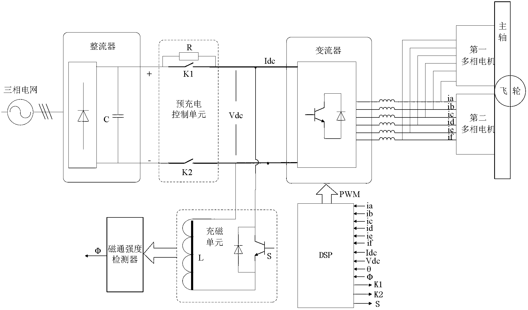
[0044] Such as figure 1As shown, a magnetizer based on flywheel energy storage includes a flywheel energy storage device and a magnetization unit; wherein:

[0045] The flywheel energy storage device is used to supply power to the magnetizing unit through charging and discharging, which includes a rectifier, a converter, a controller, a motor unit and a flywheel mechanism;

[0046] The rectifier is used to convert the alternating current of the three-phase power grid into direct current; in this embodiment, the rectifier adopts an uncontrolled rectifier bridge with a three-phase six-leg structure, and each bridge arm is formed by connecting several diodes in series; the positive and negative output terminals of the rectifier...


PUM


Abstract

The invention discloses a magnetizing apparatus on the basis of flywheel energy storage. The magnetizing apparatus comprises an energy storage unit and a magnetizing unit; and the energy storage unit is a flywheel energy storage device comprising a rectifier, a converter, a controller, a motor unit and a flywheel mechanism. A flywheel energy storage technology and a magnetizing apparatus technology are combined with each other, the flywheel energy storage device is used as a high-power pulse discharge power supply and provides energy to the magnetizing unit, and obvious characteristics of high power density, long service life, capability of preventing environmental pollution and the like of a flywheel when the flywheel is used as an energy storage element are sufficiently played. Compared with the traditional capacitance magnetizing apparatus, the magnetizing apparatus has the advantages that the magnetizing apparatus is high in number of charge-discharge, long in service life and low in cost, is efficient and effectively meets requirements of actual production, and the charge-discharge time is short.

Description

technical field [0001] The invention belongs to the field of magnetization technology, in particular to a magnetizer based on flywheel energy storage. Background technique [0002] With the rapid development of motors, household electronics, computers, communications and other technologies, the demand for permanent magnet materials is increasing, and the performance requirements are getting higher and higher. At present, most permanent magnets are made of NdFeB, ferrite, AlNiCo and other materials, which have the characteristics of high coercive force and stable performance. These composite materials can only be magnetized after they are momentarily magnetized by a magnetizer with a high current. [0003] Existing magnetizers are divided into three types according to the way the magnetizing power supply is provided: pulse magnetizers, electromagnet magnetizers and capacitive magnetizers. [0004] The pulse magnetizer uses a two-phase power supply, which has low voltage and ...

Claims


Application Information

Patent Timeline
Patent Type & Authority Applications(China)
IPC IPC(8): H01F13/00H02K7/02H02K47/00H02K3/14H02M3/22
CPCY02E60/16
Inventor 杨家强尹溶森
Owner ZHEJIANG UNIV
Why Eureka
Try Eureka