Vertical friction stud welding method

A friction stud welding and stud technology, which is applied in welding equipment, non-electric welding equipment, metal processing equipment, etc., can solve the problems of difficult to break the oxide film on the surface of aluminum materials, deteriorate the joint strength, and easily produce hard and brittle problems, and achieve Simple and feasible equipment and operation

Inactive Publication Date: 2013-05-01
XI AN JIAOTONG UNIV
View PDF5 Cites 11 Cited by
  • Summary
  • Abstract
  • Description
  • Claims
  • Application Information

AI Technical Summary

Problems solved by technology

[0003] Common arc stud welding is not suitable for stud welding of dissimilar metals. The main reason is that the liquid phase produced by arc melting is difficult to be squeezed out completely. Once there is liquid phase remaining, brittle intermetallic compounds must be formed after condensation, resulting in brittle joints. change
Taking the combination of aluminum / steel as an example, due to the large difference in the properties of aluminum and steel, the following problems are prone to occur during welding: large differences in melting point and density, difficult to weld directly by fusion welding; difficult to remove the oxide film on the surface of aluminum; Joints are prone to hard and brittle intermetallic compounds, which deteriorate joint strength
The basic principle of friction stir spot welding is to use the shoulder of the non-consumable stirring tool to heat the upper plate to soften it, and use the needle to embed the lower plate to make the lower plate reflow upward and embed the high-temperature upper plate, so as to realize the embedding between the upper / lower interface. Coupling and connection, but the keyhole will remain when the pin is pulled out after soldering

Method used


Image

  • Vertical friction stud welding method
  • Vertical friction stud welding method
  • Vertical friction stud welding method

Examples


Embodiment Construction

[0040]The present invention will be further described in detail below in conjunction with specific embodiments, which are explanations of the present invention rather than limitations.

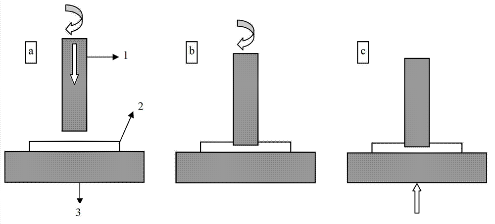
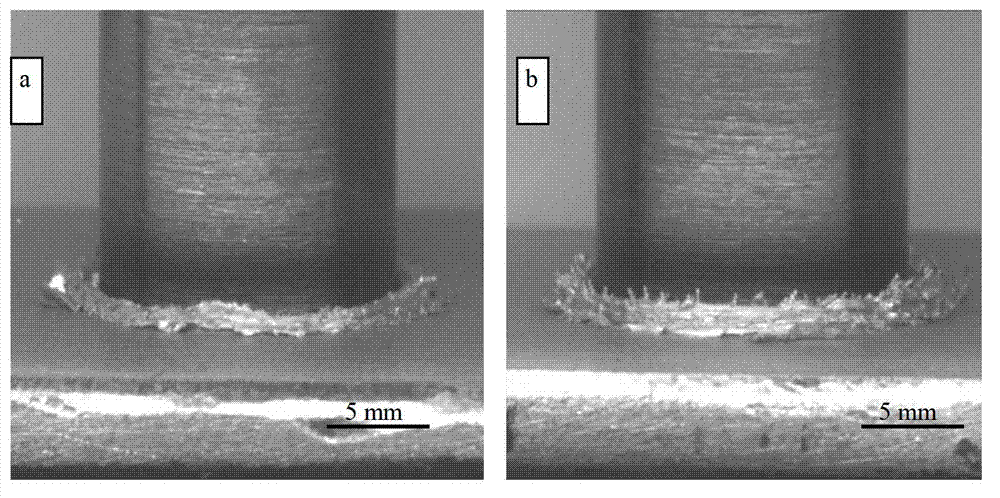
[0041] In order to solve the welding of dissimilar metal friction stud welding, if the friction stir spot welding process of aluminum plate / steel stud is used for friction stud welding of dissimilar metals, the tools used for friction stir spot welding are replaced by steel studs for stud welding, and When canceling the stud extraction process, two major problems arise:

[0042] One is that although the aluminum plate can be firmly adhered to the end of the steel stud, cracks appear in the base metal of the aluminum plate (with the continuous welding of the interface, the real instantaneous friction interface gradually transfers from the original interface to the weak base material with lower strength , the torsion cracks of the secondary friction surface appeared in the weak base metal), the ...


PUM


Abstract

The invention discloses a vertical friction stud welding method. The welding method comprises the following steps of: pressing a highly rotating stud into a board, and taking the friction heat generated by friction between the end face of the highly rotating stud and the surface layer of the board as a heat source; after the stud is pressed into the board, when a uniform overlap is formed around the stud, carrying out in-situ friction for 1-5 seconds; stopping and implementing top forge force to the board, and maintaining the top forge force at least until the stud completely stops rotating; and for the secondary friction interface cracks of dissimilar metal stud welding , carrying out on-line afresh forging and connecting by technologies of continuous top forging and classified top forging. The welding method has the characteristics that protective gas and welding flux are not needed; by carrying out heating, crushing and dispersing an interface oxidation film via the methods of expansion pressurization and in-situ friction, the board is prevented from being excessively reduced, and the welding method has the advantages of low pressure, low heat input, and capability of inhibiting intermetallic compounds; and the on-line forging method is used for repairing the secondary friction interface reverse cracks in the board with fast heat radiation.

Description

technical field [0001] The invention belongs to the technical field of metal welding and relates to a vertical friction stud welding method. Background technique [0002] Stud welding is a welding method for welding metal studs or similar rod-shaped fasteners to the surface of large-area plate or pipe workpieces (Huang Wangfu, editor-in-chief of Jin Gang. Aluminum and Aluminum Alloy Welding Guidelines [M]. Changsha: Hunan Science and Technology Press, 2004). The existing stud welding process is arc stud welding, which can only be used for welding of the same metal. At present, stud welding technology is mainly used for welding steel joints, and there are few studies on the application of aluminum alloy welding. Wu Xumin et al. (Wu Xumin, Yu Xiaohua, Nan Yi. Research on aluminum alloy capacitor discharge stud welding [J]. Mechanical Engineering Materials, 2003,27(1):44-46.) studied the use of capacitor discharge stud welding to achieve rust prevention Welding of aluminum s...

Claims


Application Information

Patent Timeline
Patent Type & Authority Applications(China)
IPC IPC(8): B23K20/12
Inventor 张贵锋焦伟民赵继鹏张建勋
Owner XI AN JIAOTONG UNIV
Why Eureka
Try Eureka