Machine tool for machining large gear in spiral bevel gear pair

A technology of spiral bevel gears and large gears, applied to components with teeth, belts/chains/gears, gear teeth, etc., can solve the problems of cost reduction, waste of resources, etc., and achieve easy chip removal, convenient loading and unloading, and cost-effective Effect

Inactive Publication Date: 2013-05-08
CHANGSHA HALIANG KAISHUAI PRECISION MASCH CO LTD
View PDF9 Cites 8 Cited by
  • Summary
  • Abstract
  • Description
  • Claims
  • Application Information

AI Technical Summary

Problems solved by technology

[0006] The object of the present invention is to provide a machine tool specially for processing large gears in spiral bevel gear pairs in view of the resource waste of existing large wheel processing machine tools, which not only improves production efficiency, but also reduces costs

Method used


Image

  • Machine tool for machining large gear in spiral bevel gear pair
  • Machine tool for machining large gear in spiral bevel gear pair
  • Machine tool for machining large gear in spiral bevel gear pair

Examples


Embodiment 1

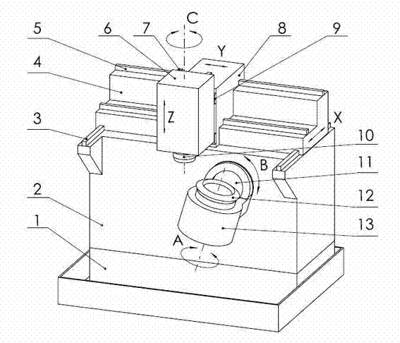
[0024] like figure 1 As shown, a machine tool for processing large gears in a spiral bevel gear pair includes a bed 2, a pallet 1 below the bed 2, a workpiece box 13 for installing a workpiece 12 to be processed, and a front end surface of the bed 2 and The cutter head or grinding wheel 10 for milling and grinding the workpiece 12 is equipped with an X-axis guide rail 3 on the top surface of the bed, and the X-axis guide rail 3 is equipped with a device that can move along the X-axis guide rail 3 under the action of the driving mechanism. The X-axis sliding table 4; the X-axis sliding table 4 is provided with a Y-axis guide rail 5, and the Y-axis guide rail 5 is equipped with a Y-axis sliding table 8 that can move along the Y-axis guide rail 5 under the action of the driving mechanism; the Y-axis slide A slide block 9 is arranged on the table 8, which is combined with the Z-axis guide rail 7 provided on the Z-axis slide table 6 to form a linear motion pair, which can make the ...

Embodiment 2

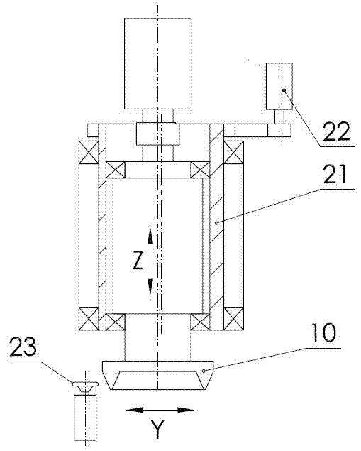
[0029] The machine tool in Example 1 is laid down 90° to the rear, the workpiece box 13 is placed on the top surface of the bed 2, the Y-axis guide rail 5 on one side of the bed 2 is arranged horizontally along the front and rear ends of the bed, and the Y-axis guide rail 5 on the Y-axis guide rail 5 The axis slide table 8 moves along the front and rear ends of the bed, and the X-axis slide table 4 in the vertical direction is arranged outside the Y-axis slide table 8, and the Z-axis guide rail is provided on the top surface of the X-axis slide table 4, and the cutter head or The grinding wheel 10 is installed on the end of the Z-axis slide table 6 close to the workpiece box 13 .

[0030] Other components of this embodiment are the same as those in Embodiment 1.


PUM


Abstract

The invention relates to a machine tool for machining a large gear in a spiral bevel gear pair and further relates to the machine tool of the large gear of the spiral bevel gear pair used for an automobile drive axle. Three sets of an X-axis guide rail, a Y-axis guide rail and a Z-axis guide rail which are vertical to each other are arranged on the top face of the machine tool body, and an X-axis slide table, a Y-axis slide table and a Z-axis slide table which move along corresponding guide rails under the action of a driving mechanism are arranged on the X-axis guide rail, the Y-axis guide rail and the Z-axis guide rail. A cutter plate or a grinding wheel is arranged at the bottom of the Z-axis slide table, and a shaft C capable of driving a machined workpiece to rotate is arranged in the Z-axis slide table. The machine tool further comprises a shaft B which penetrates through the front end face and the rear end face of the machine tool body. The front end of the shaft B is connected with a workpiece box, and the rear end of the shaft B is provided with a rotating mechanism driving the shaft to rotate B. A shaft A driving the machined workpiece to rotate is arranged in the workpiece box, and the shaft A is vertical to the shaft B. Compared with an existing device, the machine tool for machining the large gear in the spiral bevel gear pair has the advantages of being simple in structure, economic in cost, convenient to install and detach, capable of easily discharging chips and the like, and is particularly suitable for dry cutting and high-efficiency machining.

Description

technical field [0001] The invention relates to a machine tool for processing large gears in spiral bevel gear pairs, and further refers to a machine tool for processing large gears in spiral bevel gear pairs used on automobile drive axles. Background technique [0002] Most of the spiral bevel gears used in automobile drive axles are hypoid gears with relatively large transmission ratio. The pitch angle of the large gear is generally between 70°~80°, and the shape of the tooth surface of the gear tooth is very close to the cutting surface of the production wheel. In order to improve the processing efficiency, the forming method is used instead of generating motion. At present, the large gears of the automobile drive axle are processed on the general-purpose CNC gear milling and grinding machines with six axes and five linkages. It has the following disadvantages: [0003] 1. When the large gear of the automobile drive axle is processed by the generation method, only four-a...

Claims


Application Information

Patent Timeline
Patent Type & Authority Applications(China)
IPC IPC(8): B23F9/02B23F9/08
Inventor 衣红贾立冬曾亦愚
Owner CHANGSHA HALIANG KAISHUAI PRECISION MASCH CO LTD
Why Eureka
Try Eureka