Blade double-supporting variable-section nozzle ring assembly for bi-directional positioning of poking disc

A two-way positioning and dialing technology, applied in the field of auto parts, can solve the problems of jamming, deformation and movement, and the inability of the nozzle ring assembly to drive, and achieve the effect of preventing high temperature deformation and movement, and improving the stress condition.

Active Publication Date: 2013-05-08
PINGXIANG DEBO TECH CO LTD
View PDF14 Cites 14 Cited by
  • Summary
  • Abstract
  • Description
  • Claims
  • Application Information

AI Technical Summary

Problems solved by technology

However, the toggle disc supporting the variable cross-section nozzle ring assembly is not positioned reliably in the axial and radial directions, and is prone to deformation and displacement when th

Method used


Image

  • Blade double-supporting variable-section nozzle ring assembly for bi-directional positioning of poking disc
  • Blade double-supporting variable-section nozzle ring assembly for bi-directional positioning of poking disc
  • Blade double-supporting variable-section nozzle ring assembly for bi-directional positioning of poking disc

Examples


Embodiment Construction

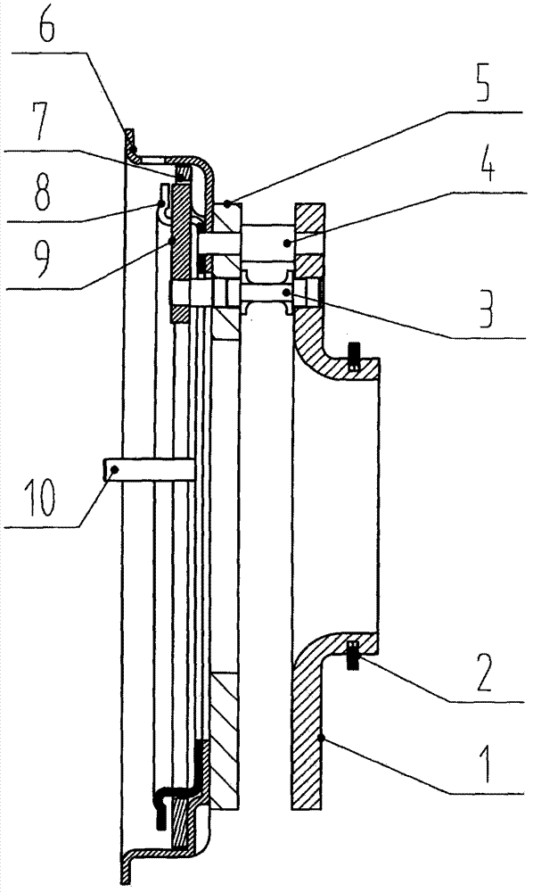
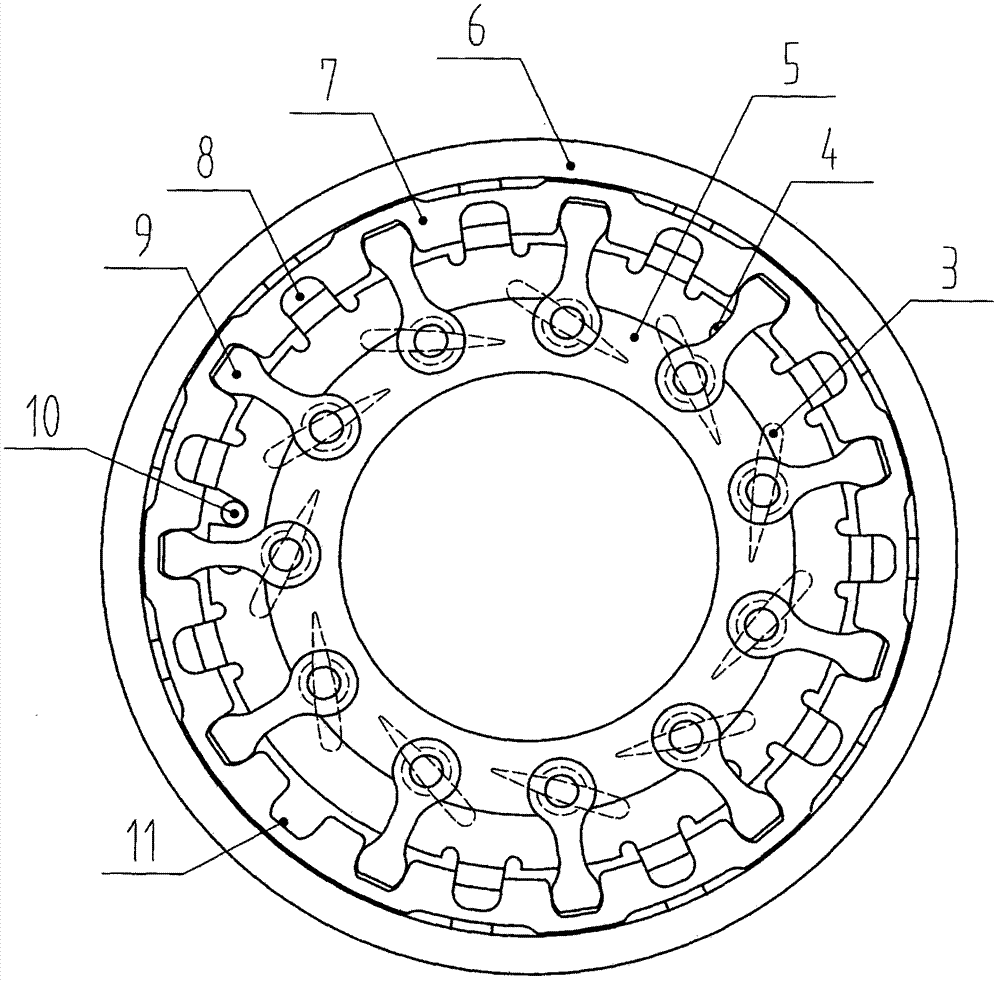
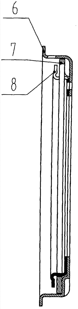
[0014] figure 2 It is embodiment 1 of the present invention, in figure 1 , figure 2 and image 3 Middle: The toggle plate 7 is placed in the limited space formed by the heat-insulating support plate 6 and the limit plate 8, and the heat-insulation support plate 6 and the limit plate 8 are welded on the mounting plate 5 through the distance sleeve 4, thereby turning The disk 7 is positioned axially and radially. In addition, the heat-insulating support disk 6 also plays a role of heat insulation, so that the temperature on the side of the shift fork 9 and the dial 7 is obviously lower than the temperature on the side of the blade 3 , to create a better working condition for the components, effectively preventing the high-temperature deformation and displacement of the dial 7; the dial 7 is provided with a notch 11 corresponding to the shift fork 9, and the shift fork 9 is directly placed on the dial 7 corresponding to the notch 11, can freely rotate and slide in the notch ...


PUM


Abstract

The invention discloses a poking disc bi-directional positioning blade double-supporting variable-section nozzle ring assembly which enables a poking disc to be reliably positioned in axial and radial directions, protects the a poking disc from deformation and mis-positioning when a load is large at high temperature, and prevents a shift fork from be dropped out of the poking disc due to the deformation or mis-positioning of the poking disc. The nozzle ring assembly is composed of a rear cover 1, a spring piece 2, a blade 3, a spacer sleeve 4, a mounting disc 5, a heat insulation support disc 6, the poking disc 7, a limiting disc 8, the shift fork 9 and a limiting pin 10. The poking disc 7 is placed in a restricted space formed by the heat insulation support disc 6 and the limiting disc 8, and the poking disc 7 is positioned in the axial and radial directions. The heat insulation support disc 6 and the limiting disc 8 are welded to the mounting disc 5 through the spacer sleeve 4, and the shift fork 9 is directly placed in a notch 11 corresponding to the poking disc 7. The head of the blade 3 is inserted into the rear cover and can freely rotate, the tail of the blade 3 is installed in the mounting disc 5 to be welded to the shift fork 9, the limiting pin 10 is directly inserted into the mounting disc 5 to be fixed, and the rear cover 1 is fixed on the mounting disc 5 through the spacer sleeve 4. The rear cover 1, the mounting disc 5 and the blade 3 form a variable-section flow channel. In work, the poking disc 7 is subjected to external force driving. Due to the fact that the poking disc 7 is in sliding fit with the shift fork 9, when the poking disc 7 rotates, the shift fork 9 is driven to rotate, the shift fork 9 drives the blade 3 to rotate, so that a blade angle is changed, the airflow section is adjusted, and an engine can efficiently work at each power section under support of a supercharger.

Description

technical field [0001] The invention relates to an auto part, which is applied to an engine supercharger, in particular to a double-supported variable-section nozzle ring assembly of a two-way positioning vane of a dial. Background technique [0002] Turbocharging is one of the development directions of internal combustion engine technology in the world, and it is the most important way to strengthen internal combustion engines today. Turbocharging technology can greatly increase engine output power, save energy, and reduce engine exhaust pollution. The variable cross-section nozzle ring assembly is the key component of today's advanced variable geometry turbocharger. The vane angle used for the nozzle ring assembly of the engine supercharger is fixed and the vane is not adjustable. The supercharger can only make the engine To work efficiently in a certain power range, our company is the first in China to improve the structure of the nozzle ring assembly so that the angle of...

Claims


Application Information

Patent Timeline
IPC IPC(8): F01D17/16
Inventor 吴学文黎俊韬刘任梅胡强
Owner PINGXIANG DEBO TECH CO LTD
Why Eureka
Try Eureka