Ignition groove of natural gas rotary engine

A rotary engine and natural gas technology, which is applied to combustion engines, machines/engines, internal combustion piston engines, etc., can solve the problems of increased engine cost, easy loss of ignition energy, and prolonged combustion period, so as to increase the overall combustion speed and improve air leakage Phenomenon, the effect of ignition energy reduction

Inactive Publication Date: 2013-05-08
JIANGSU UNIV
View PDF5 Cites 2 Cited by
  • Summary
  • Abstract
  • Description
  • Claims
  • Application Information

AI Technical Summary

Problems solved by technology

However, due to the unidirectional rotation of the rotor engine, its internal flow field is a unidirectional flow with the direction of rotor movement, and the flow velocity is very high
This will bring about two defects at the same time: first, the gas mixture gas migration velocity in the cylinder is too high, causing the airflow velocity near the spark plug to be too large, and the ignition energy is easily lost, which makes the ignition difficult to succeed. Ignition system, which not only increases the cost of the engine but also lowers the reliability of the engine ignition system; secondly, after the ignition is successful, due to the high flow rate of the mixture, the entire flame surface will continue to move forward, that is, it is difficult to fix the rear front of the flame. Near the spark plug, it is constantly brought to the front of the combustion chamber by the high-speed airflow, so that the unburned mixture at the rear of the combustion chamber must move to the front of the flame before it can be ignited, so the combustion period is longer, and the gas migration speed is greater. The longer the time after spark ignition, the farther the position of the rear front of the flame is away from the spark plug, thereby prolonging the combustion period, and the gas cannot be fully expanded, which not only greatly increases the fuel consumption rate, but also leads to future emissions. The hydrocarbon content increased greatly
In order to generate the air vortex, its depth is generally 6mm, and its length is approximately equal to the width of the rotor pit, but the width of the ignition groove cannot meet the requirements of preventing flame quenching and preventing air leakage at the same time. Generally, these two aspects are considered at the same time, and only Use an intermediate compromise value, generally set to 4mm, which limits the improvement of engine performance to a large extent

Method used


Image

  • Ignition groove of natural gas rotary engine
  • Ignition groove of natural gas rotary engine
  • Ignition groove of natural gas rotary engine

Examples


Embodiment Construction

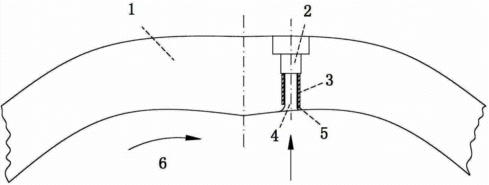
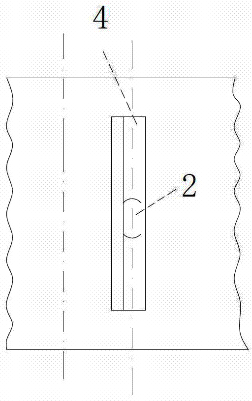
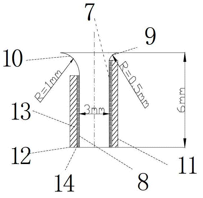
[0022] see figure 1 and 2 Open the spark plug installation hole 2 on the cylinder block 1, and install the spark plug on the bottom of the ignition groove. Since the ignition groove is designed to be suitable for generating a stable air swirl, the shape of the groove 4 must be well coupled with the direction of the airflow in the cylinder. 6 , so that the air flow enters the channel smoothly, that is, connect the front wall of the ignition tank with the cylinder profile with a small arc, and connect the rear wall with the cylinder profile with a large arc. The specific processing method is to cast with the cylinder body. When casting Rectangular pits are left on the front and rear walls to inlay silicon carbide sheets 3; in order to prevent air leakage during engine operation, the groove width is designed to be 3 mm. Propagating quenching phenomenon, inlaid silicon carbide sheet with platinum catalyst coating 5 on the wall surface of the ignition tank, under the catalytic act...


PUM


Abstract

An ignition groove of a natural gas rotary engine comprises a front wall face, a back wall face and a groove channel which is arranged between the front wall face and the back wall face. The front wall face is composed of an arc section and a non-arc section embedded with a carborundum sheet, and the back wall face is composed of an arc section and a non-arc section embedded with a carborundum sheet. The front wall face and the back wall face extend parallelly from the bottom to an air cylinder molded surface, and respectively extend from the position close to the air cylinder molded surface to form arc-shaped wall faces. The radius of an arc on one side of the front wall face is smaller than that of one side of the back wall face. A rectangular concave pit is formed in a non-arc wall face of the groove channel, and is embedded with a carborundum sheet which is coated with a platinum catalyst coating. The depth of the concave pit is equal to the thickness of the carborundum sheet, and therefore the arc sections of the front wall face and the back wall face and the non-arc sections which are embedded with the carborundum sheets of the front wall face and the back wall face are enabled to be respectively connected smoothly. According to the ignition groove of the natural gas rotary engine, the engine ignition is enabled to be convenient, combustion is promoted and accelerated by utilizing of a stable flame back frontal surface after ignition, combustion efficiency is improved, and whole performance of the engine is improved.

Description

technical field [0001] The invention belongs to the field of combination of micro-combustion technology and power machinery system ignition technology, and in particular relates to an ignition groove on a cylinder block of a natural gas rotary engine. Background technique [0002] With the development of the economy, the energy crisis and the increasing environmental pollution, people pay more and more attention to the utilization of new energy such as natural gas. The rotary engine is a new type of engine, which has many advantages that reciprocating engines cannot match, such as light weight, small size, smooth operation, low noise, and good high-speed performance. Rotary engines are better suited to burning gaseous fuels due to the overall unidirectional flow inside their combustion chambers. Therefore, natural gas rotary engine has become an important research direction of internal combustion engine due to its advantages of high efficiency and cleanliness. However, due...

Claims


Application Information

Patent Timeline
Patent Type & Authority Applications(China)
IPC IPC(8): F02B53/12
CPCY02T10/17Y02T10/12
Inventor 潘剑锋范宝伟刘杨先邵霞陈瑞
Owner JIANGSU UNIV
Why Eureka
Try Eureka