Method for determining and compensating engine blow-through air

An engine and air technology, applied to engine components, combustion engines, engine control, etc., can solve problems such as difficult to maintain catalyst balance and adjust cylinder air-fuel ratio, so as to improve conversion efficiency and reduce vehicle emissions

Active Publication Date: 2013-05-15
FORD GLOBAL TECH LLC
View PDF7 Cites 11 Cited by
  • Summary
  • Abstract
  • Description
  • Claims
  • Application Information

AI Technical Summary

Problems solved by technology

However, with a speed-density control system, it is difficult to maintain catalyst bal

Method used


Image

  • Method for determining and compensating engine blow-through air
  • Method for determining and compensating engine blow-through air
  • Method for determining and compensating engine blow-through air

Examples


Embodiment Construction

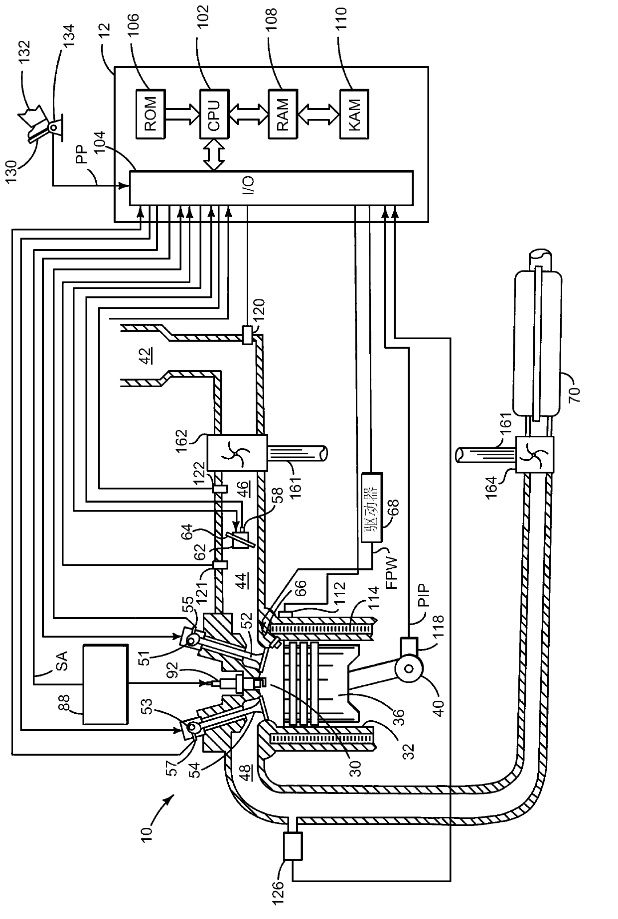
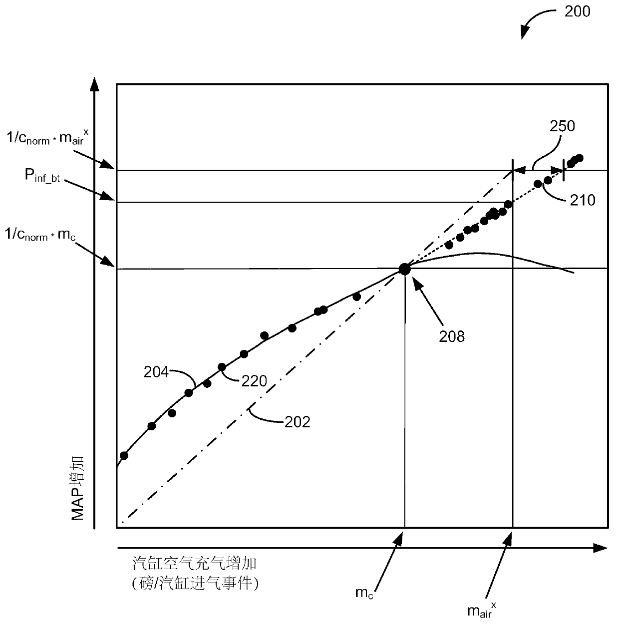
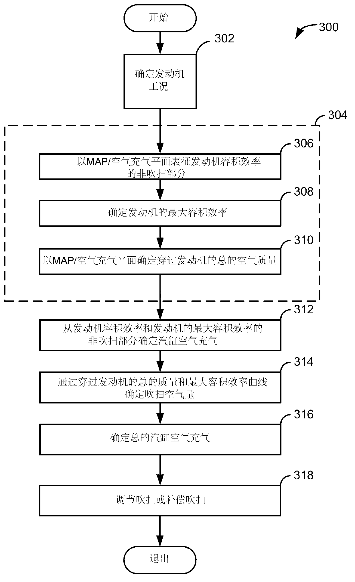
[0014] The purpose of the present invention is to determine the purge of engine cylinders. figure 1 An example system for determining cylinder purge is shown. The system includes a turbocharger that operates with a mixture of spark-ignited air and gasoline, alcohol, or a mixture of gasoline and alcohol. However, in other examples, the engine may be a compression ignition engine, such as a diesel engine. figure 2 A sample graph of the simulation is shown, which is the basis for determining the cylinder purge. image 3 Shows an example method for determining and adjusting cylinder purge.

[0015] reference figure 1 , Through the electronic engine controller 12 control including multiple cylinders ( figure 1 Only one cylinder) of the internal combustion engine 10 is shown. The engine 10 includes a combustion chamber 30 and a cylinder wall 32 in which a piston 36 is located and connected to the crankshaft 40. Combustion chamber 30 is shown as communicating with intake manifold 44 a...


PUM


Abstract

A method for determining cylinder blow-through air via engine volumetric efficiency is disclosed. In one example, the method provides a way to adjust cylinder blow-through to promote and control a reaction in an exhaust after treatment device. The approach may simplify cylinder blow-through calculations and improve engine emissions via providing improved control of constituents reaching an exhaust after treatment device.

Description

【Technical Field】 [0001] The invention relates to a method of determining and compensating for engine scavenging. 【Background technique】 [0002] Turbocharged and supercharged engines compress air into the engine to increase engine power. Compared to a naturally aspirated engine, the air compressed during the engine cycle provides an increased cylinder air charge. In addition, the cylinder fuel charge can be increased as the cylinder air charge increases in order to increase the amount of energy produced when the fuel and air are combusted during the cylinder cycle. However, during the time period when the intake valve and exhaust valve of the cylinder are opened at the same time, the air may flow directly from the engine intake manifold to the engine exhaust manifold without participating in the combustion in the cylinder. The air that does not participate in combustion and flows directly from the intake manifold to the exhaust manifold is called blow-through. [0003] The fres...

Claims


Application Information

Patent Timeline
IPC IPC(8): F02D43/00
CPCF02B2075/125F02B33/34F02D41/182F01N2560/025F01N3/021F02D2041/001F02D13/0261Y02T10/18F02B33/00F02D41/029F02B37/18Y02T10/47F02D23/02F02B25/145F02B37/16F02D2200/0402Y02T10/144F02D13/0219F01N2430/00F02D41/0062F01N2560/08Y02T10/123F02D43/00F02D2200/0411F02D41/0007F02D2200/0406Y02T10/12Y02T10/40
Inventor D·G·海格纳M·J·扬科维奇陈德修A·Y·卡尼克
Owner FORD GLOBAL TECH LLC
Why Eureka
Try Eureka