Light-emitting diode (LED) lamp unit with high heat-radiating performance and modular high-power LED lamp thereof

A technology of LED lamp units and LED lamps, applied in lighting and heating equipment, cooling/heating devices of lighting devices, lighting devices, etc., can solve the problems of limited heat dissipation surface, single heat dissipation direction, low efficiency, etc., and achieve heat conduction and Heat dissipation, reduce the number of thermal resistance layers, and improve the effect of heat dissipation

Inactive Publication Date: 2015-03-04
石振宇
View PDF7 Cites 0 Cited by
  • Summary
  • Abstract
  • Description
  • Claims
  • Application Information

AI Technical Summary

Problems solved by technology

Although such a heat dissipation structure of LED lights is stable and reliable in electricity transmission, there are deficiencies in the heat dissipation structure: (1) The heat dissipation direction is single, and the efficiency of heat conduction is low
Because most of the heat of the LED lamp chip 2 is conducted to the heat dissipation unit through the heat sink 3, and then to the atmosphere through the heat dissipation unit, and the heat dissipation fins 5 used in the existing heat dissipation unit are generally bonded by the heat dissipation substrate 51 and the heat dissipation surface of the LED. , the heat dissipation fins 52 are arranged at intervals perpendicular to the heat dissipation substrate 51, such as figure 1 As shown, that is, only heat dissipation ribs 52 are provided in the heat conduction direction of the LED lamp, and the heat dissipation surface is limited; (2) The number of thermal resistance layers is large, that is, most of the heat emitted by the LED lamp chip 2 passes through the solder h, the heat sink 3, and the circuit Plate 4, heat sink 5 of thermal conductive glue and other multiple media can be conducted to the heat dissipation unit, which weakens the heat conduction efficiency; (3) In the case of no forced air flow, the heat dissipation efficiency is not high, especially when it is assembled into a high-power LED lamp Cooling efficiency is very uneven
Because the heat dissipation fins 52 are arranged along the direction of heat conduction, in the absence of forced air flow, the area close to the heat dissipation substrate 51 is often a dead angle of air flow, and it is difficult for cold air to replenish this area, thereby affecting the heat dissipation fins 5. cooling efficiency

Method used


Image

  • Light-emitting diode (LED) lamp unit with high heat-radiating performance and modular high-power LED lamp thereof
  • Light-emitting diode (LED) lamp unit with high heat-radiating performance and modular high-power LED lamp thereof
  • Light-emitting diode (LED) lamp unit with high heat-radiating performance and modular high-power LED lamp thereof

Examples


Embodiment 1

[0041] Figure 2 to Figure 10 The first embodiment of the high-power LED lamp unit body with high heat dissipation performance and the modularized high-power LED lamp of the present invention and the installation process of the LED lamp are shown. The core problem of the existing large-scale LED lamp design is heat dissipation, and the basic principle of heat dissipation is that the fewer layers from the chip to the air structure, the better, the thinner the layer thickness, the better, the larger the layer area, the better, and the thermal conductivity of the material The higher the better.

[0042] The LED lamp of the present invention can be composed of a plurality of LED lamp units 15 to form a modularized high-power LED lamp, and the LED lamp includes a plurality of LED lamp units 15 . Each LED unit body 15 includes a lens 141, a chip 14, an electrode 151, a gold wire (not shown in the figure), a heat sink, and the heat sink includes a frustum-shaped insulating substrate...

Embodiment 2

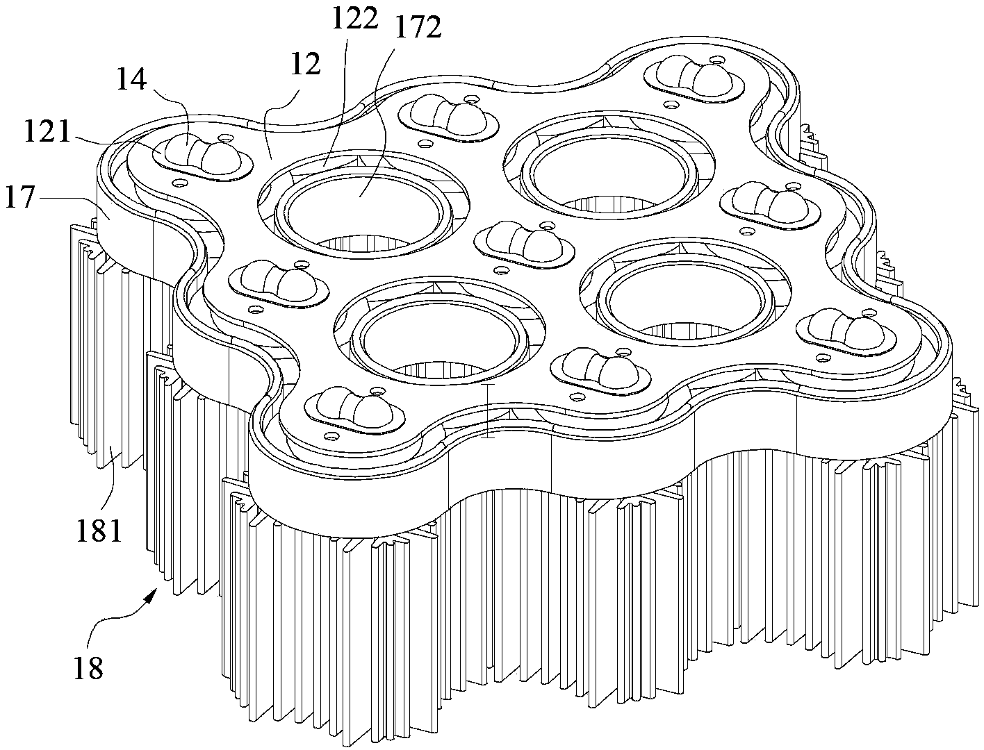
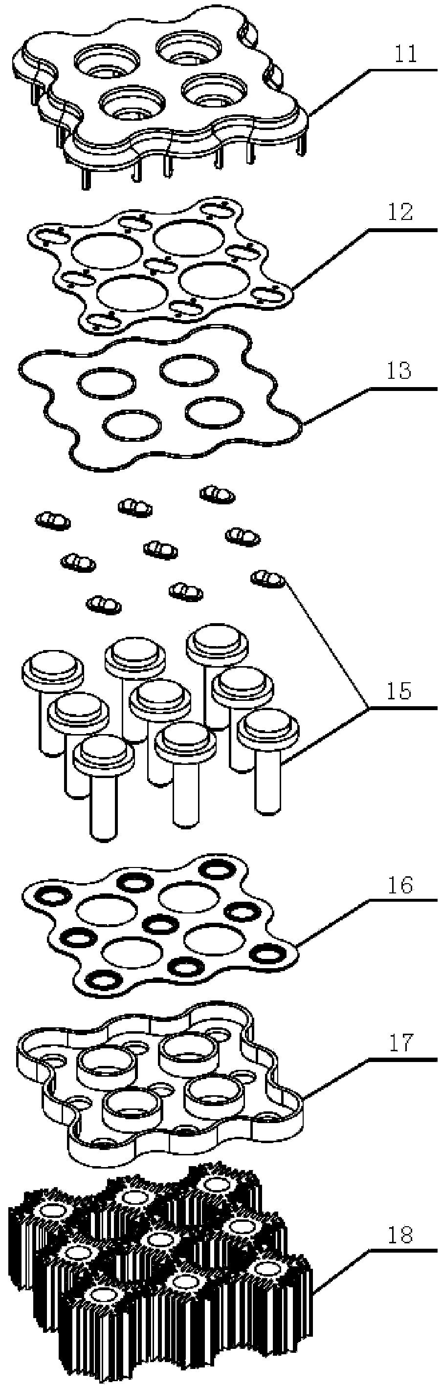
[0049] Such as Figure 11 Shown is the second embodiment of the high-power LED lamp unit body with high heat dissipation performance and its modular high-power LED lamp of the present invention. The difference between the second embodiment and the first embodiment is that this embodiment shows An LED lamp composed of 4 LED lamp unit bodies 15 and 4 heat dissipation units 18, the upper housing 11 is made of PC transparent material (so Figure 11 not shown in), thus facilitating the divergence of light. The upper housing 11 is provided with a cooling interval hole 111 ( Figure 11 not shown in ), the lower housing 17 is provided with a heat dissipation interval hole 172, and the circuit board 12 is provided with a heat dissipation interval hole 122, corresponding to the holes of the circuit board 12, rubber gasket 13 and rubber pad 16, used To be loaded into the upper casing 11 and the lower casing 17 correspondingly. The above-mentioned heat dissipation interval holes corres...

Embodiment 3

[0051] Such as Image 6 , Figure 12 Shown is a specific embodiment of the high-power LED lamp unit body with high heat dissipation performance of the present invention. The difference between the third embodiment and the first embodiment is that this embodiment is an LED lamp unit body 15, including a lens 141 And chip 14, electrode 151, gold wire (not marked in the figure), heat sink, this heat sink includes a circular truncated ceramic insulating substrate 152 and a cylindrical aluminum heat conducting rod 154, in this embodiment Among them, the top of the cylindrical heat conducting rod 154 is also provided with an aluminum heat conducting disc 153, the heat conducting disc 153 and the heat conducting rod 154 are integrally designed, the insulating substrate 152 is welded on the heat conducting disc 153 at the top of the heat conducting rod 154, the heat conducting disc 153 The diameter of the disk 153 is slightly larger than that of the insulating substrate 152 , and pla...


PUM


Abstract

The invention discloses a light-emitting diode (LED) lamp unit with a high heat-radiating performance. The LED lamp unit with the high heat-radiating performance comprises a lens, a chip, an electrode, gold wires and a heat sink. The heat sink comprises an insulation base plate in a circular truncated cone shape, and a cylindrical heat conducting bar. The insulation base plate is welded at the top end of the heat conducting bar. The lens, the chip, the electrode and the gold wires are welded on the insulation base plate. Therefore, heat generated by the chip is conducted to the heat conducting bar below the insulation base plate through the insulation base plate and is radiated. The invention further discloses a modular high-power LED lamp formed by LED lamp units. The LED lamp unit directly conducts the heat generated by the chip to a heat radiating unit through the heat sink to radiate, the number of heat resistance layers is reduced, and therefore heat radiating efficiency is improved so as to improve the reliability of the LED lamp and prolong the service life of the LED lamp.

Description

technical field [0001] The utility invention relates to an LED lamp and a lamp thereof, in particular to a high-power LED lamp unit module with high heat dissipation performance and a modularized high-power LED lamp composed of the same. Background technique [0002] LED (Light Emitting Diode) is a kind of light-emitting diode that uses current to flow forward to the p-n junction coupling of light-emitting semiconductors, prompting electrons to recombine with holes in the P region, and releasing excess energy in the form of light and heat, thereby converting electrical energy A source of light and heat. It has many advantages such as low-voltage power supply, low energy consumption, strong applicability, high stability, short response time, no pollution to the environment, multi-color light, long service life and durability, etc. It can be used continuously for 100,000 hours, and its life It is 100 times longer than ordinary incandescent bulbs. Therefore, it has become the ...

Claims


Application Information

Patent Timeline
Patent Type & Authority Patents(China)
IPC IPC(8): F21S2/00F21V29/00F21Y101/02F21V29/503F21V29/76
Inventor 石振宇
Owner 石振宇
Why Eureka
Try Eureka