Process and device for forming micro-bulge oil film on surface of workpiece under nano particle jet flow condition

A nanoparticle and workpiece surface technology, which is used in grinding/polishing safety devices, manufacturing tools, metal processing equipment, etc. The internal relationship between the surface morphology of the lubricating oil film and the formation mechanism of the nano-particle oil film have not been established to achieve the effects of good heat transfer performance, enhanced heat transfer performance, and reduced friction.

Active Publication Date: 2015-04-08
QINGDAO TECHNOLOGICAL UNIVERSITY
View PDF9 Cites 0 Cited by
  • Summary
  • Abstract
  • Description
  • Claims
  • Application Information

AI Technical Summary

Problems solved by technology

[0013] Although many scholars have carried out theoretical analysis and experimental research on nano-micro-lubrication, and have done a lot of demonstrations and experiments, they have not organically linked nano-micro-quantity lubrication with the surface morphology of workpieces, and have not established the relationship between the formation of lubricating oil film and The internal relationship between the surface morphology of the workpiece, and the formation mechanism of the oil film on the surface of the asperity workpiece during nano-particle micro-lubrication grinding, and the advantages of lubrication and heat dissipation of the micro-quantity grinding wheel / workpiece interface cannot be brought into play by the nano-particle jet.

Method used


Image

  • Process and device for forming micro-bulge oil film on surface of workpiece under nano particle jet flow condition
  • Process and device for forming micro-bulge oil film on surface of workpiece under nano particle jet flow condition
  • Process and device for forming micro-bulge oil film on surface of workpiece under nano particle jet flow condition

Examples


Embodiment Construction

[0044] Below in conjunction with accompanying drawing, the present invention is described:

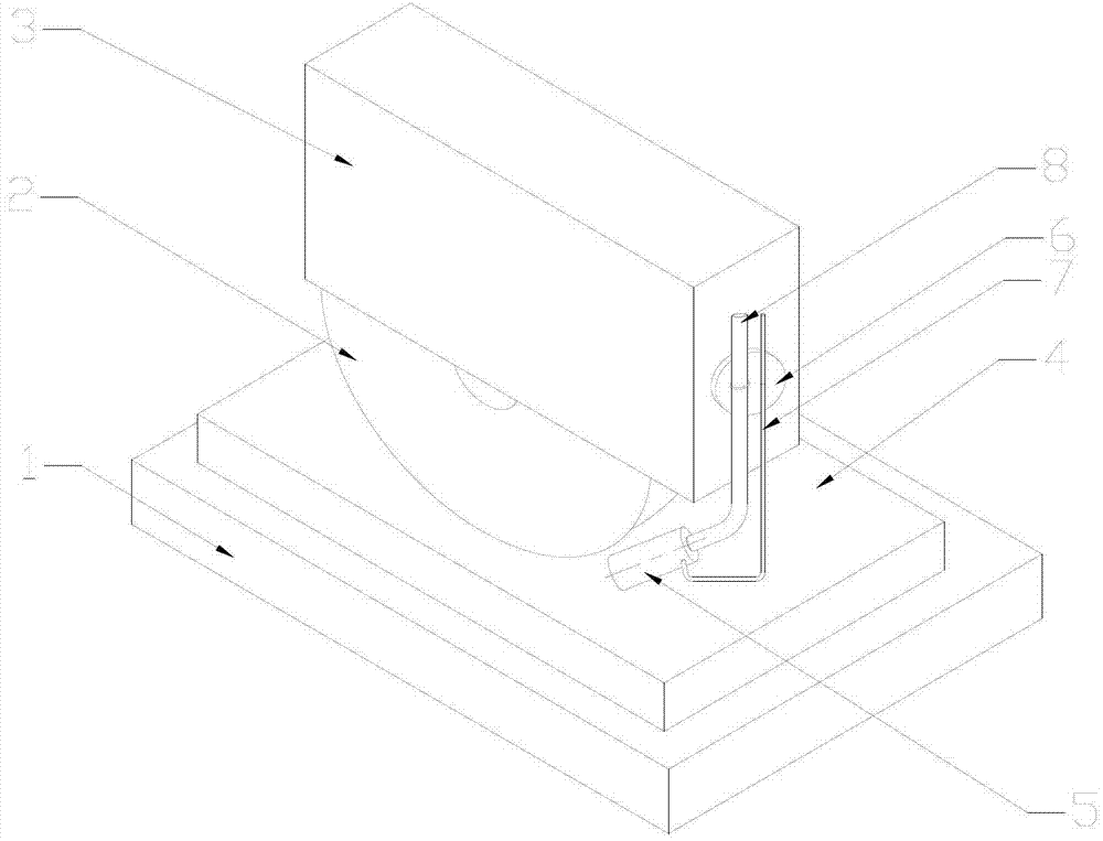
[0045] like figure 1 As shown, the workpiece 4 is installed on a part of the workbench 1, the magnetic fixed suction cup 6 is adsorbed on the side of the grinding wheel cover 3, and the compressed air delivery pipe 7 and the nanofluid delivery pipe 8 are fixed by the magnetic fixed suction cup 6. One end of the nanofluid delivery pipe 8 is connected to the nanofluid inlet of the nozzle 5, and the other end is connected to the turbine flowmeter II22. One end of the compressed gas delivery pipe 7 is connected to the compressed gas inlet of the nozzle 5, and the other end is connected to the turbine flowmeter I21.

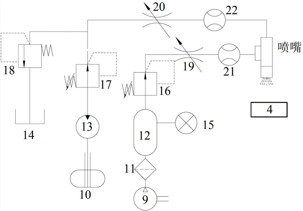
[0046] like figure 2 As shown, the air circuit is composed of an air compressor 9, a filter 11, an air storage tank 12, a pressure regulating valve I16, a throttle valve I19, and a turbine flowmeter I21. Nanofluid storage tank 10, hydraulic pump 13, pressure regulating val...


PUM

PropertyMeasurementUnit
particle sizeaaaaaaaaaa
kinematic viscosityaaaaaaaaaa
particle diameteraaaaaaaaaa

Abstract

The invention relates to a process and a device for forming a micro-bulge oil film on a surface of a workpiece under nano particle jet flow condition. According to the process, the action that the nano particle jet flow micro lubrication is coupled with the a micro-bulge on the surface of the workpiece is utilized, a nano fluid is ejected to a grinding area in a higher speed under the action of compressed air, so as to form the lubrication oil film on the surface of the workpiece with the micro-bulge, thereby cooling and lubricating the grinding machining area to the maximum extent. The nano particles are adhered to the rough surface of the workpiece and have stronger cooling performance and excellent friction characteristics, so that the grinding burn is effectively solved, the surface of the workpiece is good in quality, and low-carbon, green and cleaning production with high efficiency, low consumption, environmental friendliness and resource conservation is realized. The device comprises a nano fluid supply device and a compressed air supply device, wherein the two devices are respectively connected with a nozzle through a nano fluid conveying pipe and a compressed air conveying pipe; a set distance d and an included angle alpha are maintained between the nozzle and the workpiece with the micro-bulge surface; and the nano fluid supply device and the compressed air supply device are connected with a control device.

Description

technical field [0001] The invention relates to a process and a device for forming an asperity oil film on the surface of a workpiece under the condition of nanoparticle jet flow. Background technique [0002] In the process of metal grinding, the lubrication between the grinding wheel and the surface of the workpiece is mostly boundary lubrication. Under boundary lubrication conditions, it is not that the more the amount of grinding fluid is used, the better the grinding effect is, but there is a certain range of suitable amount. The dosage range is related to the performance of the grinding fluid, the characteristics of the grinding wheel, the material of the workpiece, the microscopic appearance of the surface, and the surface roughness. In the traditional pouring grinding process, the amount of grinding fluid used is about 8400-9500ml / min. However, even with such a large amount of grinding fluid, the "air barrier layer" will hinder the flow of grinding fluid due to the ...

Claims


Application Information

Patent Timeline
Patent Type & Authority Patents(China)
IPC IPC(8): B24B55/02
Inventor 李长河贾东洲王胜张强
Owner QINGDAO TECHNOLOGICAL UNIVERSITY
Why Eureka
Try Eureka