Electronic expansion valve and machining method thereof

An electronic expansion valve and valve seat technology, applied in the field of control valves, can solve the problems of reducing the operating voltage of the electronic expansion valve and unstable opening/closing of the valve, and achieve the effects of reducing the driving voltage, reducing friction and wear, and increasing smoothness

Inactive Publication Date: 2013-05-22
ZHEJIANG SANHUA INTELLIGENT CONTROLS CO LTD
View PDF4 Cites 7 Cited by
  • Summary
  • Abstract
  • Description
  • Claims
  • Application Information

AI Technical Summary

Problems solved by technology

[0006] The purpose of the present invention is to provide an electronic expansion valve. Through the improvement of the surface treatment process, the surface of the part itself can be directly hardened and wear-resistant, so that the hardness and wear resistance of the fitting parts of the nut and the screw rod can be

Method used


Image

  • Electronic expansion valve and machining method thereof
  • Electronic expansion valve and machining method thereof
  • Electronic expansion valve and machining method thereof

Examples


Embodiment Construction

[0039] In order to enable those skilled in the art to better understand the technical solutions of the present invention, the present invention will be further described in detail below in conjunction with the accompanying drawings and specific embodiments.

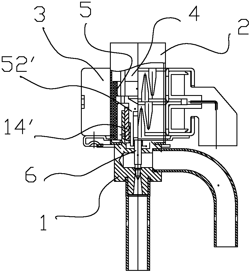
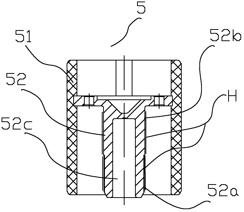
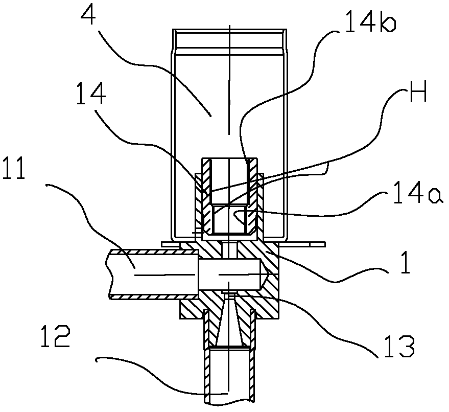
[0040] figure 1 It is a schematic diagram of a typical electronic expansion valve; figure 2 A structural schematic diagram of the magnetic rotor part of the electronic expansion valve provided by the present invention; image 3 It is a schematic diagram of installing the nut of the electronic expansion valve on the valve body provided by the present invention.

[0041] Such as figure 2 and image 3 shown and combined as figure 1 . The electronic expansion valve includes a valve seat 1. On the valve seat 1, there are channel inlet 11 and outlet 12 for refrigerant circulation. The valve seat 1 is also processed with a valve port 13 connecting the inlet 11 and the outlet 12. The nut 14 passes through the interference ...


PUM

PropertyMeasurementUnit
Depthaaaaaaaaaa

Abstract

The invention discloses an electronic expansion valve and a machining method thereof and relates to the technical field of control valves. The electronic expansion valve comprises a valve seat (1), a nut (14), a sleeve (2) and a coil (3), wherein the nut (14) and the sleeve (2) are fixed on the valve seat (1), the coil (3) is fixed on an outer side of the sleeve, the sleeve (2) and the valve seat (1) form a cavity (4), a magnet rotor component (5) which senses the magnetic field of the coil and rotates is arranged in the cavity (4), and the lower end of the magnet rotor component (5) is provided with a valve rod (6). The magnet rotor component (5) is provided with a screw rod (52), and a first thread section (52a) and a second thread section (14a) are respectively arranged on the screw rod (52) and the nut (14). The electronic expansion valve and the machining method thereof are characterized in that the first thread section (52a) of the screw rod (52) is provided with a hardened layer which is treated through a micro particle injection process or a precision sand blasting process. A surface of a component is conducted with hardening and anti-wear treatment directly, the fatigue strength and the surface hardness of the surface of the nut and the screw rod are improved, the service life of the component is greatly prolonged and the working precision is improved greatly.

Description

technical field [0001] The invention relates to the technical field of control valves, in particular to an electronic expansion valve for regulating fluid flow and a processing method thereof. Background technique [0002] In air conditioners, refrigerators, heat pump water heaters and various refrigeration / heating equipment, electronic expansion valves are usually used to regulate the flow of fluid. [0003] in such as figure 1 In the schematic structure diagram of a typical electronic expansion valve shown, the electronic expansion valve usually includes a valve seat 1, a nut 14' fixed on the valve seat 1, a sleeve 2 connected to the valve seat 1, and a nut 14' fixed on the outside of the sleeve. The coil 3, the valve seat 1 is provided with an inlet, an outlet and a valve port connecting the inlet and the outlet, the sleeve 2 and the valve seat 1 are welded to form a closed cavity 4, and the cavity 4 is provided with a magnetic field of the coil 3 And the rotating magne...

Claims


Application Information

Patent Timeline
IPC IPC(8): F16K31/50F16K31/44F25B41/06B24C1/10F25B41/345F25B41/35
CPCY02B30/72Y02B30/70
Inventor 不公告发明人
Owner ZHEJIANG SANHUA INTELLIGENT CONTROLS CO LTD
Why Eureka
Try Eureka