Controlling system of steam injection boiler gas leakage and boiler safe operation

A steam injection boiler and control system technology, applied in the direction of controlling combustion, lighting and heating equipment, etc., can solve problems such as boiler automatic flameout, boiler safe operation, leakage, etc., to achieve the effect of eliminating lag and coupling and improving control accuracy

Active Publication Date: 2013-05-22
PETROCHINA CO LTD
View PDF7 Cites 6 Cited by
  • Summary
  • Abstract
  • Description
  • Claims
  • Application Information

AI Technical Summary

Problems solved by technology

[0004] (2) Indoor gas pipeline leakage
[0005] (3) Boiler body leakage
The reasons are: in the early stage of gas boiler design or installation, the construction was not carried out according to the relevant technical requirements (for example: if the boiler model wall is not welded strictly); Seam cracks and seals are not tight); the gas boiler vibrates greatly during operation, the weld seam is desoldered or the furnace wall insulation layer is cracked; the fire viewing hole, explosion-proof door, manhole door, etc. are not closed tightly; the boiler automatically turns off when it is running, etc.;
[0006] (4) Burner leakage
The reasons are: frequent movement of these parts may cause the switch to be inflexible and not tightly closed, or the connection parts are loose due to the large vibration during the operation of the boiler, and natural gas leaks, or the control, adjustment, measurement and other parts are of poor quality and not tightly closed. Air leakage; or leakage due to aging of flanges, sealing gaskets, sealants, etc.
[0008] However, there is currently no control system specifically for gas leakage and safe operation of boilers for thermal recovery and steam injection.

Method used


Image

  • Controlling system of steam injection boiler gas leakage and boiler safe operation
  • Controlling system of steam injection boiler gas leakage and boiler safe operation
  • Controlling system of steam injection boiler gas leakage and boiler safe operation

Examples


Embodiment Construction

[0023] The following will clearly and completely describe the technical solutions in the embodiments of the present invention with reference to the accompanying drawings in the embodiments of the present invention. Obviously, the described embodiments are only some, not all, embodiments of the present invention. Based on the embodiments of the present invention, all other embodiments obtained by persons of ordinary skill in the art without making creative efforts belong to the protection scope of the present invention.

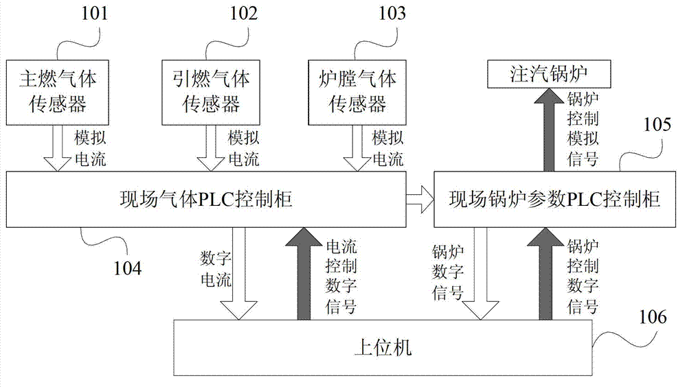
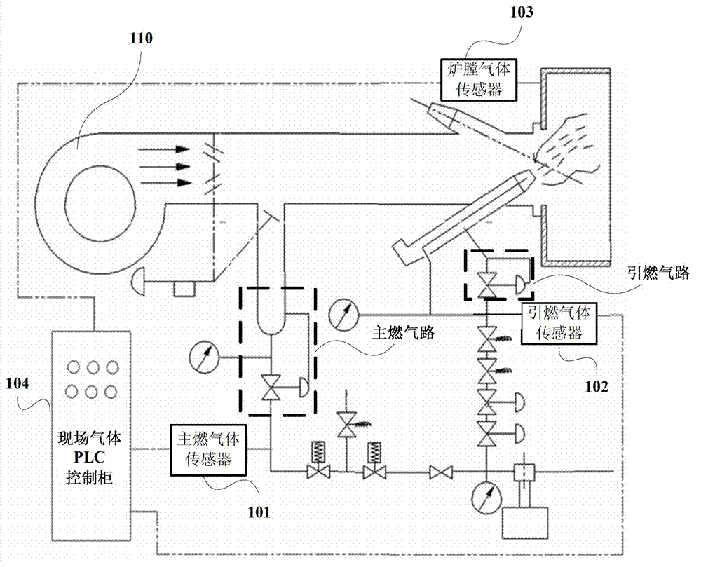
[0024] figure 1 It is a structural schematic diagram of a control system for gas leakage of a steam injection boiler and safe operation of the boiler according to an embodiment of the present invention. As shown in the figure, the control system of this embodiment includes: main gas sensor 101, pilot gas sensor 102, furnace gas sensor 103, on-site gas PLC control cabinet 104, on-site boiler parameter PLC control cabinet 105 and host computer 106. figure 2 It...


PUM


Abstract

The invention discloses a controlling system of steam injection boiler gas leakage and boiler safe operation. The controlling system of the steam injection boiler gas leakage and the boiler safe operation comprises a main gas sensor, an ignition gas sensor, a furnace gas sensor, a scene gas programmable logic controller (PLC) controlling cabinet, a scene boiler parameter PLC controlling cabinet and an upper computer. The main gas sensor is arranged in a main gas circuit. The ignition gas sensor is arranged in an ignition gas circuit. The furnace gas sensor is arranged in the steam injection boiler furnace. A main gas circuit simulated electric current, an ignition gas circuit simulated electric current and a furnace simulated electric current are converted to a digital electric current signal by the scene PLC controlling cabinet and are transmitted to the upper machine. According to the controlling system of the steam injection boiler gas leakage and the boiler safe operation, interlocking controlling of gas detection and the boiler operation is achieved, namely the boiler is not permitted to start and operate and ignite under the condition that the natural gas leaks or the breakdown is not excluded. The boiler controlling hysteresis and the coupling are eliminated by taking advantage of the sensor controlling at the same time, thus controlling precision is improved.

Description

technical field [0001] The invention relates to the field of oil thermal recovery, in particular to the field of gas safety monitoring of steam injection boilers, in particular to a control system for gas leakage of steam injection boilers and safe operation of boilers. Background technique [0002] In addition to the natural gas leakage in the gas boiler room caused by the illegal operation of employees and natural and external forces, the main reasons are as follows: [0003] (1) Leakage of outdoor buried gas pipelines. The reasons are: the construction quality is not up to standard or the pipeline is corroded and perforated; [0004] (2) Indoor gas pipeline leakage. The reasons are: the construction quality is not up to standard during construction or the long-term operation pipeline is corroded; [0005] (3) The boiler body leaks. The reasons are: in the early stage of gas boiler design or installation, the construction was not carried out according to the relevant t...

Claims


Application Information

Patent Timeline
Patent Type & Authority Applications(China)
IPC IPC(8): F23N5/00
Inventor 许宝燕张红朋马庆曲明艺梁兴李琦李娟娟任鹏承
Owner PETROCHINA CO LTD
Why Eureka
Try Eureka