

Pixel unit drive circuit, pixel unit drive method, pixel unit and display device
A driving circuit and pixel unit technology, which is applied in the field of pixel unit driving circuit, pixel unit and display device, can solve the problems of OLED current inconsistency, influence on display effect, uneven luminous brightness of pixel unit, etc., to ensure driving voltage and driving current, The effect of ensuring uniformity and improving quality
- Summary
- Abstract
- Description
- Claims
- Application Information
AI Technical Summary
Problems solved by technology
Method used
Image

Examples
Embodiment 1
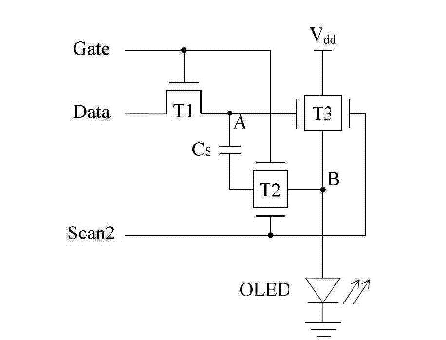
[0056] Such as figure 2 As shown, this embodiment provides a pixel unit driving circuit for driving a light emitting device to emit light, which includes a first thin film transistor T1, a second thin film transistor T2, a third thin film transistor T3 and a storage capacitor Cs.
[0057] Wherein, the first thin film transistor T1 includes a gate, a first pole and a second pole, the gate is connected to the scan line Gate, the first pole is connected to the data line Data, and the second pole is connected to the first Node A is connected.
[0058] The second thin film transistor T2 includes two gates, a first pole and a second pole, that is, the second thin film transistor is a double-gate TFT, one of the two gates is connected to the scanning line Gate, The other gate is connected to the second control line Scan2, the first electrode is connected to the storage capacitor Cs, and the second electrode is connected to the second node B.
[0059] The third thin film transistor...
Embodiment 2
[0093] Such as Figure 5 As shown, this embodiment provides a pixel unit driving circuit for driving OLED to emit light.
[0094] The difference between the pixel unit driving circuit in this embodiment and the pixel unit driving circuit in Embodiment 1 is that: the first node A is connected to the scanning line Gate.
[0095] This embodiment also provides a pixel unit comprising an OLED and the above-mentioned pixel unit driving circuit connected thereto.
[0096] This embodiment also provides a display device comprising a plurality of the above-mentioned pixel units distributed in a matrix.
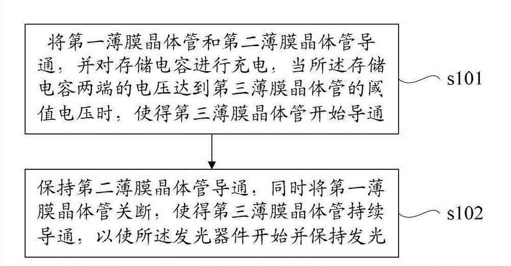
[0097] Such as Figure 6 As shown, this embodiment also provides a pixel unit driving method applied to the above pixel unit driving circuit, including the following steps:
[0098] s201. Turn on the first thin film transistor T1 and the second thin film transistor T2, and pre-charge the first thin film transistor T1, so that the first node A has an initial voltage.
[0099] Specifi...
Embodiment 3
[0128] Such as Figure 8 As shown, this embodiment provides a pixel unit driving circuit for driving OLED to emit light.
[0129] The difference between the pixel unit driving circuit in this embodiment and the pixel unit driving circuit in Embodiment 1 is that: the driving circuit further includes a fourth thin film transistor T4, which includes a gate, a first pole and a second pole; The gate is connected to the first control line Scan1, the first pole is connected to the second node B, and the second pole is grounded.
[0130] This embodiment also provides a pixel unit comprising an OLED and the above-mentioned pixel unit driving circuit connected thereto.
[0131] This embodiment also provides a display device comprising a plurality of the above-mentioned pixel units distributed in a matrix.
[0132] The pixel unit driving circuit described in this embodiment and the matrix formed by the OLEDs connected to it are as follows: Figure 9 As shown, the display device includ...
PUM
 Abstract
Description
Claims
Application Information