Insulated wire

An insulated wire and insulating coating technology, applied in the direction of insulated cables, insulators, insulated conductors, etc., can solve the problems of damage and deterioration of the insulating coating, and achieve the effects of excellent heat resistance and high partial discharge inception voltage.

Inactive Publication Date: 2013-05-29
HITACHI METALS LTD
View PDF11 Cites 9 Cited by
  • Summary
  • Abstract
  • Description
  • Claims
  • Application Information

AI Technical Summary

Problems solved by technology

In addition, since a higher voltage such as an inverter surge voltage is applied to the coil in the electrical equipment, there is a problem that the insulating coating may be deteriorated or damaged due to the occurrence of partial discharge.

Method used


Image

  • Insulated wire
  • Insulated wire
  • Insulated wire

Examples


Embodiment

[0049] Hereinafter, the present invention will be described in more detail based on examples, but the present invention is not limited to these examples.

[0050] (Preparation of Examples 1-9 and Comparative Examples 1-3)

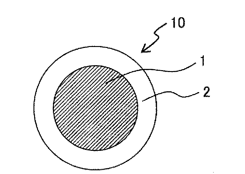
[0051] Use a copper wire with an outer diameter of 1.25 mm as a conductor, and use an extruder to extrude and coat the resin composition shown in Table 1 on the outer layer of the copper wire to produce figure 1 Insulated wires of the shape shown. The resin temperature during extrusion coating was set to about 360° C., and the thickness of the insulating coating layer (first extrusion coating layer) was set to about 100 μm. Table 1 shows the compositions of the resin compositions constituting the extrusion coating layers of Examples 1-9 and Comparative Examples 1-3. In addition, in Table 1, the apparent viscosity of the resin (A) is measured at a temperature of 380°C and a shear rate of 10 sec using a capillary rheometer (manufactured by Toyo Seiki Co., L...


PUM

PropertyMeasurementUnit
shear viscosityaaaaaaaaaa
thicknessaaaaaaaaaa
thicknessaaaaaaaaaa

Abstract

There is provided an insulated wire including a wire conductor and at least one extruded insulation layer formed on the wire conductor. The at least one extruded insulation layer is made of a phase separated resin composition including: a resin (A) including polyether ether ketone as a continuous phase; and a resin (B) with a relative dielectric constant of 2.6 or less as a dispersed phase.

Description

technical field [0001] The present invention relates to an insulated electric wire used in coils of electric equipment such as a rotating electric machine and a transformer, and particularly relates to an insulated electric wire provided with an insulating coating layer including an extruded coating layer. Background technique [0002] Insulated electric wires (enamelled insulated electric wires) used in coils of electric equipment such as rotating machines and transformers are generally formed as follows: Conductors formed in a cross-sectional shape (for example, circular, rectangular) conforming to the purpose and shape of the coil The outer layer is formed with a single or multiple layers of insulating coating. In terms of the method of forming the insulating coating layer, there are: a method of applying an insulating paint obtained by dissolving a resin in an organic solvent on the conductor and baking it; extruding a resin composition prepared in advance to coat the co...

Claims


Application Information

Patent Timeline
Patent Type & Authority Applications(China)
IPC IPC(8): H01B7/02
CPCH01B3/441H01B7/0275H01B3/427H01B3/442Y10T428/2933
Inventor 山崎孝则百生秀人森下滋宏
Owner HITACHI METALS LTD
Why Eureka
Try Eureka