A combined permanent magnet with enhanced regional magnetic field strength

A technology of magnetic field strength and permanent magnets, applied in the direction of magnetic objects, magnetic materials, permanent magnets, etc., can solve the problems of occupied volume, demagnetization failure of permanent magnets, low production efficiency, etc., to solve serious demagnetization, improve power generation efficiency, and bond high efficiency effect

Inactive Publication Date: 2016-03-09
TONGJI UNIV
View PDF6 Cites 3 Cited by
  • Summary
  • Abstract
  • Description
  • Claims
  • Application Information

AI Technical Summary

Problems solved by technology

However, the bonding strength is not high, the curing time is long, and the production efficiency is low. In addition, the skeleton is often bulky and takes up a lot of unnecessary volume, so this method is not suitable for the preparation of combined permanent magnets for micro-generators.
[0004] Welding is a high-efficiency, high-strength metal material connection method. However, powder metallurgy permanent magnets are powder sintered. Conventional welding methods cannot connect permanent magnets. Even the connected parts will be peeled off from other parts, resulting in fracture
Moreover, the temperature of the molten pool is extremely high and the heat-affected zone is large in the conventional welding method, which causes serious demagnetization and failure of the permanent magnet.
In recent years, a series of high-energy beam welding with small heat-affected zone and high energy density (such as laser welding, ion beam welding and electron beam welding, etc.) has been developed, which may solve the problem of welding permanent magnets. However, this method is used for assembly Permanent magnets are used to prepare combined permanent magnets with enhanced regional magnetic field strength but no mention

Method used


Image

  • A combined permanent magnet with enhanced regional magnetic field strength
  • A combined permanent magnet with enhanced regional magnetic field strength
  • A combined permanent magnet with enhanced regional magnetic field strength

Examples


Embodiment 1

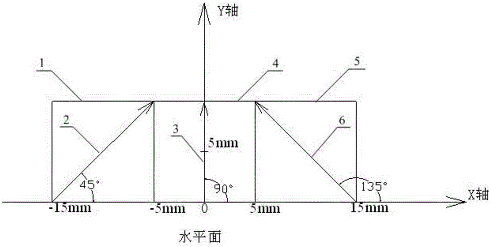
[0028] Positive combined permanent magnet: a cuboid combined permanent magnet formed by parallel welding of three sub-magnets of the same size, 10mm×10mm×10mm, cubic N50 NdFeB permanent magnets, such as figure 1 Shown: a cuboid combined permanent magnet formed by parallel welding of three cube-shaped sub-magnets 1, 4, and 5 of the same size. The combined permanent magnet is placed on a horizontal plane, and the magnetic field direction 3 of the middle sub-magnet is perpendicular to The horizontal plane is upward, the magnetic field direction 2 of the left terminal magnet is parallel to the direction where the welding seam on the upper surface of the left terminal magnet 1 forms an angle with the horizontal plane at an angle of 45°, and the magnetic field direction 6 of the right terminal magnet is parallel to the upper surface of the right terminal magnet 5 The direction where the diagonal surface where the weld is located and forms an angle of 135° with the horizontal plane; ...

Embodiment 2

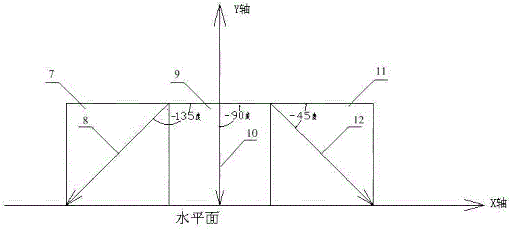
[0032] Negative combined permanent magnet: a cuboid combined permanent magnet formed by parallel welding of three sub-magnets of the same size 10mm×10mm×10mm cubic N50 NdFeB permanent magnets 7, 9 and 11, such as figure 2 As shown: when the combined permanent magnet is placed on a horizontal plane, the magnetic field direction 10 of the middle sub-magnet is perpendicular to the horizontal plane downward, and the magnetic field direction 8 of the left terminal magnet is parallel to the diagonal plane where the welding seam on the upper surface of the left terminal magnet 7 is located. In the direction of a negative 135° angle with the horizontal plane, the magnetic field direction 12 of the right terminal magnet is parallel to the diagonal surface where the welding seam on the upper surface of the right terminal magnet 11 is located and is at a negative 45° angle with the horizontal plane.

[0033] The welding is electron beam welding, laser welding or ion beam welding; the wel...


PUM


Abstract

The invention relates to a regional magnetic field intensity enhancing combination permanent magnet. The regional magnetic field intensity enhancing combination permanent magnet comprises the following two sizes: a positive size combination permanent magnet and a negative size permanent magnet. Sub-magnets with single magnetizing direction are combined based on different magnetic field directions, and then are effectively welded to a combination permanent magnet through a manner of high energy density beam welding; the combination permanent magnet which is prepared is used for the regional magnetic field enhancing combination permanent magnet of a minitype permanent magnet generator, therefore a high effective magnetic field design is realized, and working efficiency of the minitype permanent magnet generator is prominently improved.

Description

technical field [0001] The invention relates to a combined permanent magnet with enhanced regional magnetic field strength, which belongs to the field of preparation of combined permanent magnets. Background technique [0002] Today, advanced industrial and energy fields require more motors and generators that are smaller but more efficient, and permanent magnet motors and generators are becoming more and more popular with the birth of high-performance strong magnets represented by NdFeB. more attention. The reason why these high-performance strong magnets can promote the development of permanent magnet motors and generators is that they can generate stronger air-gap magnetic fields than ordinary permanent magnets, thereby improving their efficiency. However, even with such high-performance permanent magnets, there is still a limit to the strength of the magnetic field they can provide. Can the air-gap magnetic field be increased by some other means? The answer is yes. Ac...

Claims


Application Information

Patent Timeline
Patent Type & Authority Patents(China)
IPC IPC(8): H01F7/02H01F1/057H01F41/02
Inventor 严鹏飞严彪
Owner TONGJI UNIV
Why Eureka
Try Eureka