

Production line for self-heat-insulation building blocks for walls
A self-insulating block and production line technology, which is applied in ceramic molding workshops, ceramic molding machines, manufacturing tools, etc., can solve problems affecting production efficiency, increased production costs, and poor load-bearing capacity, so as to reduce slurry waste and save energy. Production cost, the effect of reducing production cost
- Summary
- Abstract
- Description
- Claims
- Application Information
AI Technical Summary
Problems solved by technology
Method used
Image

Examples
Embodiment 1
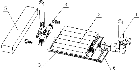
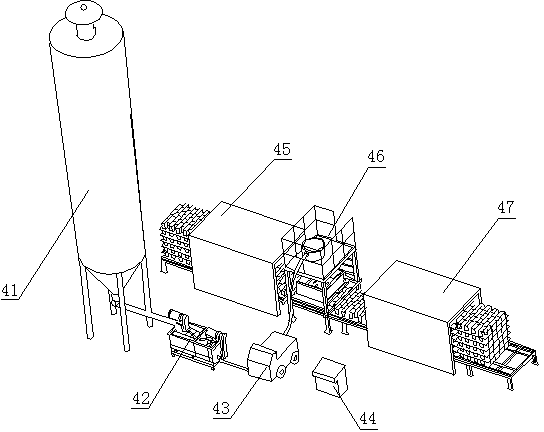
[0030] Such as figure 1 , figure 2 , image 3 , Image 6 As shown, a production line of wall self-insulating block equipment includes a hollow brick production system 1, a steam curing system 2, a transfer system 3, a foam concrete pouring system 4 and an automatic control system 6, and the steam curing system 2 passes through the The rotating system 3 is respectively connected with the hollow brick production system 1 and the foamed concrete pouring system 4, and the automatic control system 6 is connected with the hollow brick production system 1, the steam curing system 2, the foamed concrete pouring system 4 and the transfer system through control lines. System 3 is connected. Described foam concrete pouring system 4 comprises cement silo 41, mixer 42, slurry generation pump 43, discharge mechanism 45, material injection mechanism 46, code material mechanism 47 and console 44, and described console 44 communicates with control circuit respectively The cement silo 41, ...
Embodiment 2
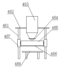
[0032] The difference between embodiment two and embodiment one is: as Figure 4 , Figure 7 As shown, the material control device is a manipulator, and the manipulator includes a horizontal telescopic rod 575 arranged at the lower end of the elevating rod 571, and two mechanical fingers 576 are respectively arranged at both ends of the horizontal telescopic rod 575. The horizontal telescopic rod 575 realizes telescopic function through a hydraulic cylinder. The lifting mechanism 467 for adjusting the distance between the injection plate 466 and the injection groove 465 and the hollow brick body is a lifting hydraulic cylinder arranged on the legs of the hollow brick body transmission platform 468 . The transfer system 3 includes a transfer rail, a turning trolley and a forklift.
Embodiment 3
[0034] The difference between embodiment three and embodiment one and embodiment two is: as Figure 5As shown, the lifting mechanism for adjusting the distance between the injection plate 466 and the injection groove 465 and the hollow brick body is a hinge rod 4671 and a telescopic hydraulic cylinder 4672 respectively hinged with the injection plate 466 and the platform 461 . The automatic control system 6 includes two consoles 44, one of which controls the foam concrete pouring system 4 independently.
[0035] The production process of the present invention is as follows: materials such as cement, water, and fine sand pass through the hollow brick body production system 1 to produce hollow brick bodies, and are transported to the steam curing system 2 through the transfer system 3 for steam curing, and the cured hollow brick bodies pass through the guide rails The trolley or forklift is transported to the discharge mechanism 45 of the foam concrete pouring system 4, the dis...
PUM
 Abstract
Description
Claims
Application Information