Waste plastic recycling system

A technology of waste plastics and feeding, applied in cleaning methods and appliances, magnetic separation, solid separation, etc., can solve the problems of increasing the utilization rate of waste plastic raw materials, high recycling costs of waste plastics, and reducing investment in cleaning equipment, so as to reduce cleaning Equipment investment, simple structure, and the effect of reducing investment

Active Publication Date: 2013-06-05
广州凌富机电有限公司
View PDF6 Cites 25 Cited by
  • Summary
  • Abstract
  • Description
  • Claims
  • Application Information

AI Technical Summary

Problems solved by technology

[0006] The invention overcomes the complex structure and cumbersome process of the existing waste plastic recycling system, which requires water washing of waste plastic raw materials, high waste plastic recycling cost, low utilization rate of plastic raw materials, and harmful gas generated in the waste plastic recycling process will pollute Due to the lack of environment, a waste plastic recycling system is provided, which has a sim

Method used


Image

  • Waste plastic recycling system
  • Waste plastic recycling system
  • Waste plastic recycling system

Examples


Embodiment 1

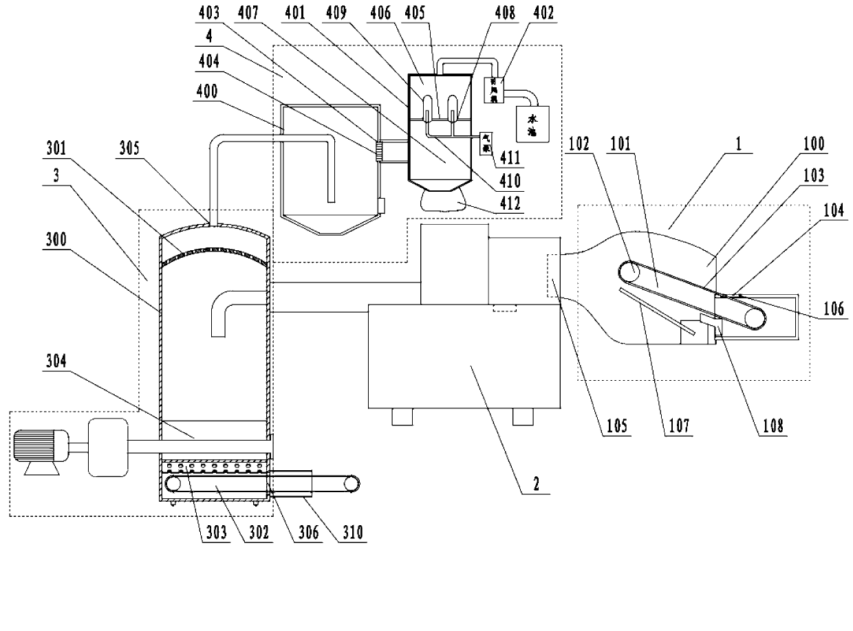
[0029] Embodiment 1: a kind of waste plastic recycling system (see attached figure 1 ), especially suitable for the recycling of waste plastics in the paper industry, including a feeding device 1, an extrusion device 2, a discharge device 3 and a dust suction device 4 connected in sequence. The feeding device comprises a closed feeding housing 100, and an inclined feeding conveying mechanism 101 is provided in the feeding housing. The feeding conveying mechanism includes two pulleys 102 and a conveyor belt 103 arranged on the two pulleys. Above the pulley at the feed end, the pulley at the discharge end has strong magnetism. The feed housing is provided with a rectangular feed port 104 and a discharge port 105 connected to the extrusion device. The side wall of the feed port is covered with a strong magnetic block 106. The bottom of the conveyor belt in the feed housing is provided with an inclined stop. Plate 107, one end of the baffle is close to the pulley position of the ...

Embodiment 2

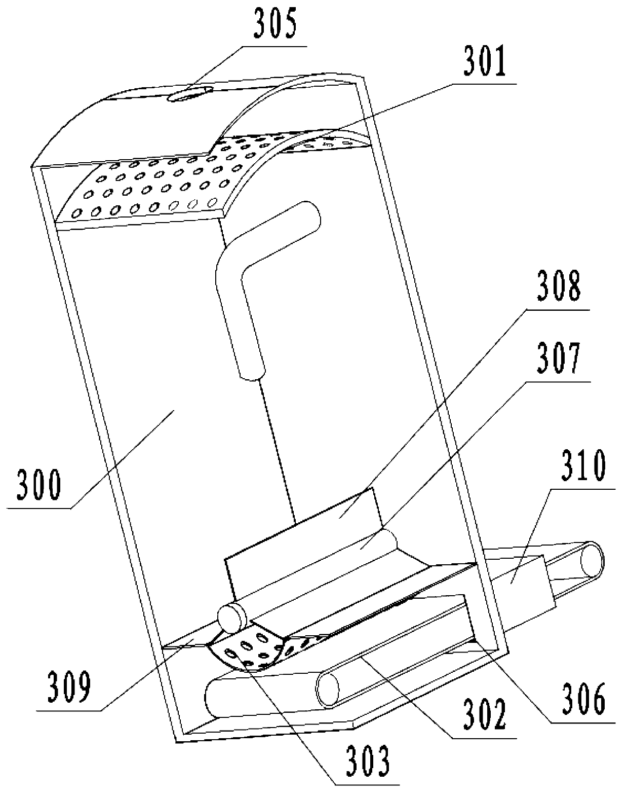
[0033] Embodiment 2: a kind of waste plastic recycling system (see attached image 3 ), its structure is similar to that of Example 1, the main difference lies in the discharge device (see attached Figure 4 )Structure. The upper end of the crushing mechanism in the discharge shell is fixedly connected with a vertical cooling cylinder 311. The cooling cylinder includes an inner cylinder 312 and an outer cylinder 313. The gap between the inner cylinder and the outer cylinder forms a cooling cavity 314, and the upper and lower ends of the cooling cavity are closed. The outer cylinder is provided with two water inlet pipes 315 communicating with the cooling chamber, and the inner cylinder wall is provided with several high-pressure injection holes 316 communicating with the cooling chamber, and the two water inlet pipes are connected with a high-pressure water pump. The axis of the high-pressure injection hole intersects the axis of the inner cylinder. Other structures are the ...

Embodiment 3

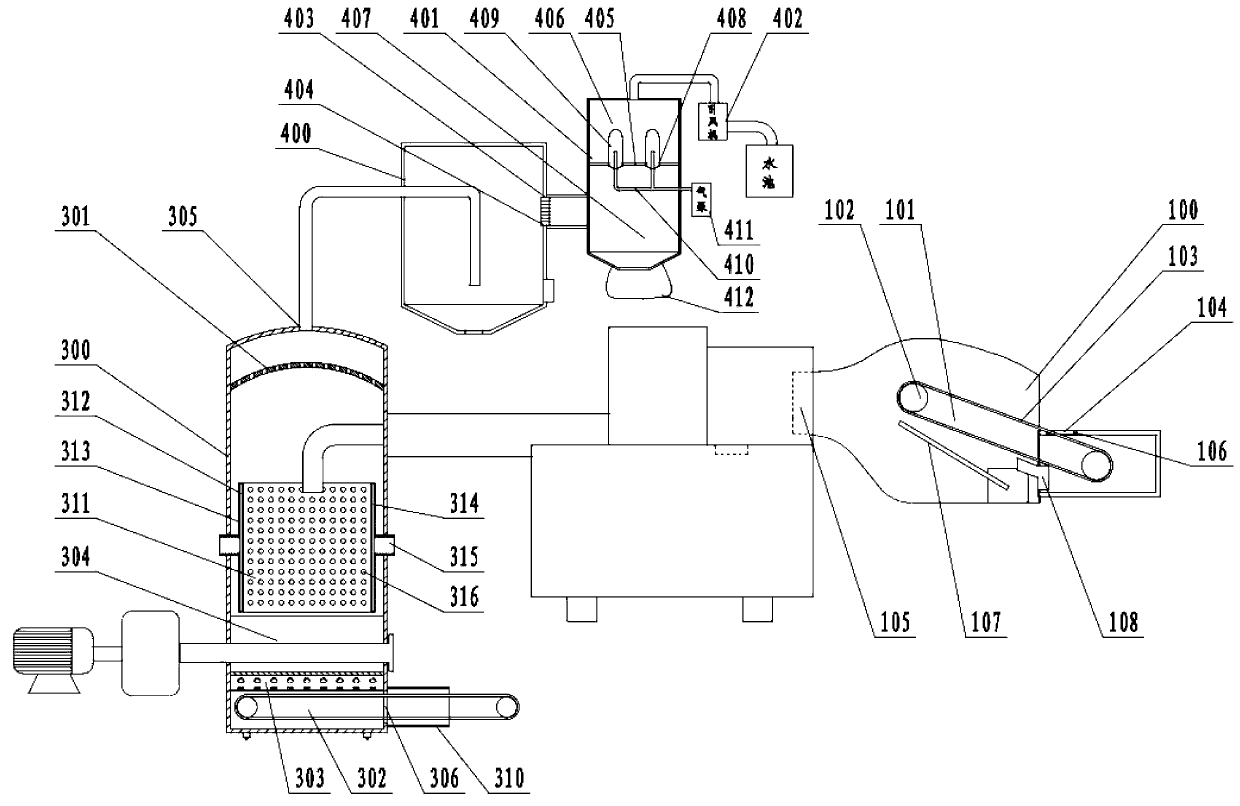
[0034] Embodiment 3: a kind of waste plastic recycling system (see attached Figure 5 ), its structure is similar to that of Example 2, the main difference lies in the discharge device (see attached Figure 6 ) structure and the structure of the feeding device. A filter cartridge 317 is fixedly connected above the cooling cylinder in the discharge housing, the axis of the filter cartridge is perpendicular to the axis of the cooling cylinder, and the two ends of the filter cartridge are fixedly connected to the inner wall of the discharge housing. Outer cylinder 319, there is a gap between the inner cylinder and the outer cylinder, several filter holes 320 are evenly distributed on the cylinder wall of the inner cylinder, and an extrusion filter is arranged on the cylinder wall of the outer cylinder close to the position directly above the cooling cylinder. Hole 321. On the outer wall of the discharge shell near the two ends of the filter cartridge, there are slag discharge h...


PUM


Abstract

The invention discloses a waste plastic recycling system, and aims to overcome the defects that in an existing waste plastic recycling system, structure is complex, process is cumbersome, washing of waste plastic raw materials is needed, recycling cost of waste plastics is high, a utilization rate of the plastic raw materials is low, and harmful gas produced in the recycling process of the waste plastics can pollute environment. The waste plastic recycling system comprises a feeding device, an extrusion device, a discharging device and a dust suction device which are connected in sequence. The feeding device enables the waste plastic raw materials to be delivered to the extrusion device without washing, investment of washing devices is eliminated, recycling cost of the waste plastics is reduced, and the utilization rate of the waste plastic raw materials is increased. Due to the fact that the discharging device is designed in a closed mode, the waste gas is led into the dust suction device, and the environment is not polluted. Besides, flue-gas temperature is low in the recycling process of the waste plastics, no harmful gas such as dioxin is produced, and the waste plastic recycling system is environment-friendly.

Description

technical field [0001] The invention relates to a waste plastic treatment device, more specifically, it relates to an energy-saving and environment-friendly waste plastic recycling system. [0002] Background technique [0003] With the continuous strengthening of people's awareness of environmental protection, waste plastics have been well recycled. At present, the recovered waste plastics are generally washed with water first, dried after cleaning, and finally heated and melted. The melted waste plastics are extruded through a plastic extruder, and then traction granulated. On the one hand, this treatment method needs to wash the waste plastic raw materials with water, and needs to use cleaning equipment, which increases the investment in equipment and process steps, and greatly increases the recycling cost of waste plastics. And after cleaning, many waste plastic raw materials that can be used will also be cleaned and precipitated and cannot be used, which greatly...

Claims


Application Information

Patent Timeline
IPC IPC(8): B29B9/06B08B15/04B03C1/22
Inventor 费洪福
Owner 广州凌富机电有限公司
Why Eureka
Try Eureka