Method and device for industrial furnace atmosphere automatic combustion control

An industrial furnace and atmosphere technology, which is applied in the direction of furnace control devices, furnaces, furnace components, etc., can solve the problems that the combustion atmosphere control technology cannot meet, and the real-time automatic control of the combustion atmosphere cannot be realized, so as to improve fuel combustion efficiency and increase furnace temperature. , the effect of reducing exhaust emissions

Inactive Publication Date: 2013-06-05
WUXI KAITIAN ENVIRONMENTAL PROTECTION TECH
View PDF6 Cites 14 Cited by
  • Summary
  • Abstract
  • Description
  • Claims
  • Application Information

AI Technical Summary

Problems solved by technology

These series of measures cannot achieve real-time automatic control of the combustion atmosphere, and require a long period of detection and analysis of the atmosphere, and the adjustment of the air-fuel ratio parameters is also corrected by the operator based on experience.
[0003] The cur...

Method used


Image

  • Method and device for industrial furnace atmosphere automatic combustion control

Examples


Embodiment 1

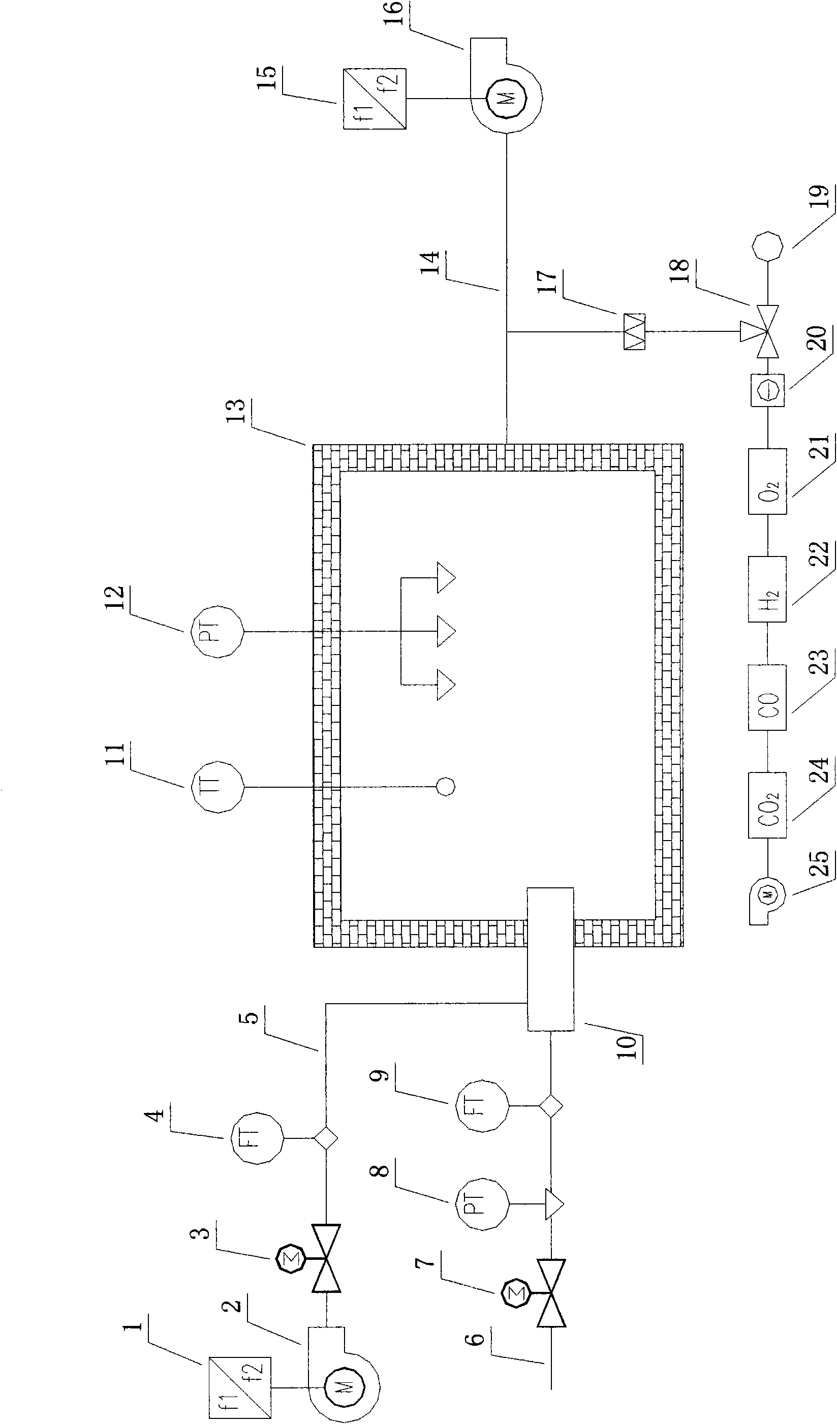
[0030] Such as figure 1 As shown, it is a mixed combustion mode industrial furnace commonly used in the industry at present. The present invention installs a sampling probe at the flue gas outlet 14 of the industrial furnace, and performs coarse filtration 17, and uses a gas sampling pump 25 to continuously extract the flue gas, and its flue gas sampling The flow rate is controlled within the range of 3-5L / min, and a filter water removal and impurity removal device 20, a timing backflushing and timing verification valve 18, and a verification backflushing gas source 19 are installed on the flue gas sampling pipe. Pass the flue gas through three gas chambers in turn, and test the O in the flue gas respectively. 2 , H 2 , CO content, and finally connected to an infrared gas analyzer to detect CO in the flue gas 2 content, and then calculated according to the characteristics of the fuel, the characteristics of the industrial furnace and the production process, with H 2 , the C...

Embodiment 2

[0036] An automatic control device for industrial furnace atmosphere combustion, its control structure is as attached figure 1 Shown, comprise industrial furnace furnace body 13, be provided with induced draft fan 16 in the flue 14 of described industrial furnace furnace body 13, described induced draft fan 16 is controlled by induced air flow controller 15, be provided with in industrial furnace furnace body 13 A burner 10, a temperature detector 11, a three-point pressure detector 12 and a smoke filter 17. The burner 10 is connected to a combustion control mechanism, and the smoke filter 17 is connected to a smoke detection mechanism.

[0037] The combustion control mechanism includes a fuel pipeline 6 and a combustion-supporting air pipeline 5 connected in parallel. The combustion-supporting air pipeline 5 is connected in series with a combustion-supporting air blower 2, a combustion-supporting air regulating valve 3 and a combustion-supporting air flow detector 4. The combu...


PUM


Abstract

The invention relates to the technical field of industrial furnace combustion control, and particularly provides a method and a device for industrial furnace atmosphere automatic combustion control. The method comprises the following steps: measuring contents of O2, CO2, H2, and CO in flue gas which is after being burned by using an on-line real-time sampling detection method, analyzing combustion atmosphere data, adjusting industrial furnace combustion-supporting wind-fuel flow and induced air flue gas flow by using an industrial furnace combustion atmosphere mathematical model, controlling the combustion atmosphere and controlling furnace chamber pressure to enable the combustion to be carried out in a controllable atmosphere on the premise that industrial furnace manufacturing technique requirements are met, and controlling a combustion flue gas flow direction and the furnace chamber pressure to be in stable conditions. Compared with the prior art, the method and the device for the industrial furnace atmosphere automatic combustion control have the advantages that self-adjusting and automatic control of the combustion atmosphere can be achieved, disturbance pipe network fuel fluctuations to the control can be automatically corrected, no manual intervention is needed in a control process, and due to the fact that the combustion atmosphere of a heating furnace can be automatically controlled, effects of stable combustion, combustion quality improvement, fuel conservation, control of heating furnace oxidation burning loss, reduction of flue gas emission and improvement of industrial furnace thermal efficiency are achieved.

Description

technical field [0001] The invention relates to the technical field of industrial furnace combustion control, and specifically provides an automatic control method and device for industrial furnace atmosphere combustion. Background technique [0002] At present, the atmosphere combustion control of industrial furnaces is mainly based on air-fuel (coal) ratio control: most industrial furnaces set fixed air-fuel ratio parameters according to process requirements for open-loop control; some industrial furnaces use zirconia to measure the oxygen concentration in the flue gas , and adjust the air-fuel ratio parameters accordingly; some kilns also use a calorific value meter to analyze the fuel calorific value characteristics, and use this as a reference to manually correct the air-fuel ratio parameters. None of these series of measures can realize the real-time automatic control of the combustion atmosphere, all of which require a long period of detection and analysis of the atmo...

Claims


Application Information

Patent Timeline
IPC IPC(8): F27D7/06F27D19/00
Inventor 李向阳屈镔
Owner WUXI KAITIAN ENVIRONMENTAL PROTECTION TECH
Why Eureka
Try Eureka