

Spectrum light splitting imaging system light path based on volume hologram grating component light splitting
A volume holographic grating and imaging system technology, which is applied in the field of optical path of spectral spectroscopic imaging system, can solve the problems of narrow free spectral range, complex structure and adjustment, difficult installation and adjustment, etc., and achieves compact structure, simple installation and adjustment, and utilization of light energy. added effect
- Summary
- Abstract
- Description
- Claims
- Application Information
AI Technical Summary
Problems solved by technology
Method used
Image

Examples
Embodiment Construction
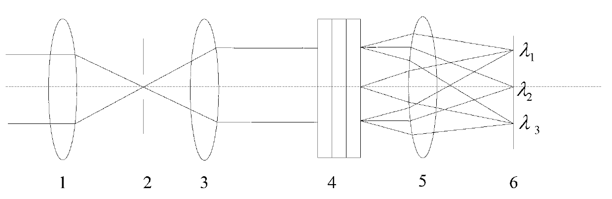
[0014] Such as figure 1 The distant object shown is imaged at the slit 2 through the telescopic objective lens 1, and the light entering the slit passes through the collimating objective lens 3 and reaches the holographic beam splitting component 4 for light splitting, and the parallel beam is imaged at the image plane by the imaging objective lens 5 after being split. , received by the CCD detector 6.
[0015] The collimating objective lens and the imaging objective lens are important components of the spectral imaging system. The collimating objective lens collimates the light passing through the slit and then enters the spectroscopic device, and the imaging objective lens converges the dispersed light on the image plane. For imaging spectrometers, the energy utilization rate is an important performance index of the system. Therefore, when designing collimating objective lenses and imaging objective lenses, the relative aperture should be increased as much as possible.
[0...
PUM
 Abstract
Description
Claims
Application Information