
Atomic vapor sampling method and device based on electro-deposition and electro-heat

A technology of electrothermal atom and sample injection device, which is applied in the field of instrument analysis to achieve the effects of increasing primary ionization efficiency, reducing matrix interference and reducing working conditions

Inactive Publication Date: 2013-06-12
HOHAI UNIV
View PDF6 Cites 0 Cited by
  • Summary
  • Abstract
  • Description
  • Claims
  • Application Information

AI Technical Summary

Problems solved by technology

[0005] At present, there is no report on the use of electrodeposition-electrothermal for atomic vapor sampling in elemental analysis

Method used


Image

  • Atomic vapor sampling method and device based on electro-deposition and electro-heat
  • Atomic vapor sampling method and device based on electro-deposition and electro-heat

Examples


Embodiment 1

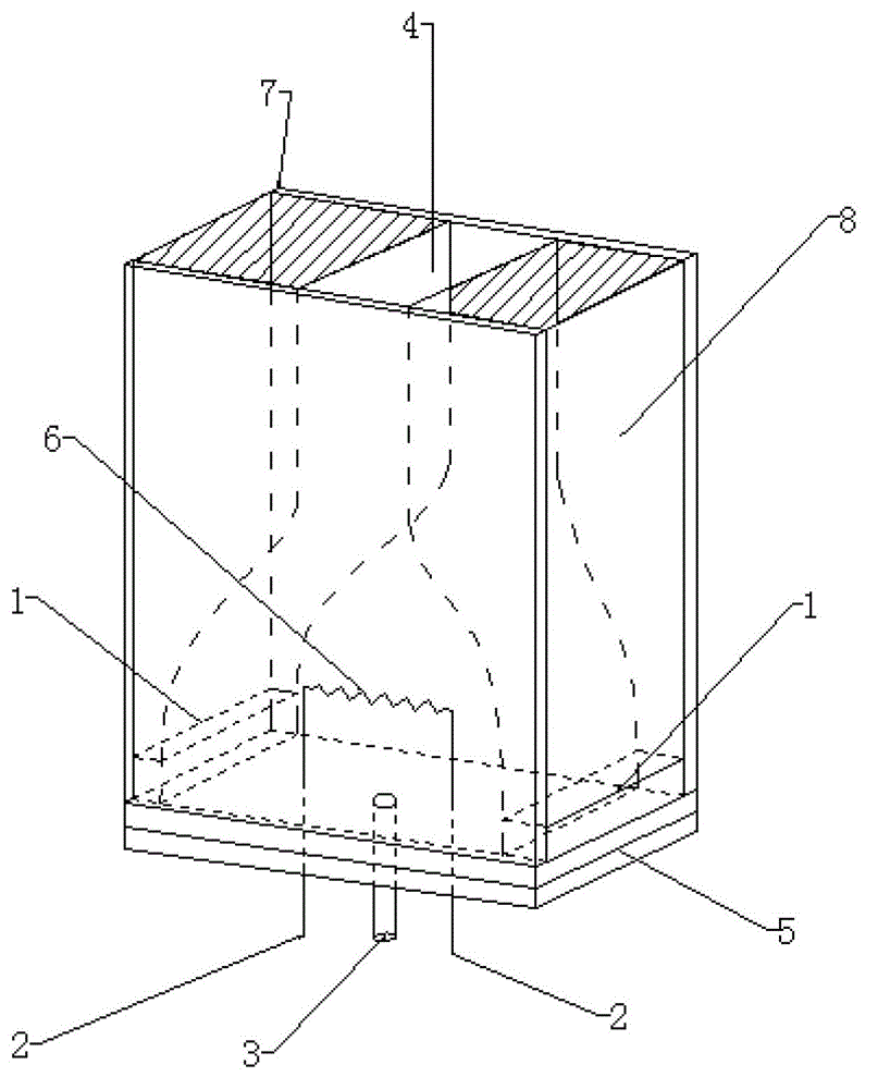
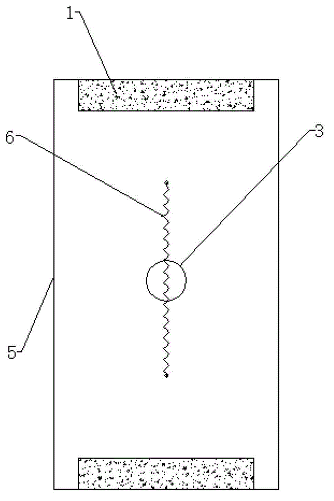
[0031] Embodiment 1: as figure 1 As shown, the evaporation chamber is composed of heat-resistant glass 7, 8 and a heat-resistant glass bottom plate 5, the sample inlet 3 and the exhaust port 4 form an air intake system, the platinum-plated electrolytic electrode 1 is at both ends of the plate, and the tungsten heating wire 6 The two ends pass through the bottom plate 5 to connect the wire 2, and the opposite side is the exhaust port 4. The power supply for heating the carrier gas through the injection port is a feedback current power supply, which can realize precise temperature control.

[0032] Standard solution Cr (Cr 3+ ) after entering from the injection port 3, enter the mixed gas of 95% argon and 5% hydrogen at 15ml / min through the injection port 3, electrolyze under the stirring of the carrier gas, and use constant potential deposition, the deposition potential is -1.3V, At this time, the two electrodes 1 are connected to the positive pole of the DC power supply thr...

Embodiment 2

[0035] Embodiment 2: as figure 1 As shown, the evaporation chamber is composed of quartz 7, 8 and a heat-resistant glass bottom plate 5, the sample inlet 3 and the exhaust port 4 form an air intake system, the platinum-plated electrolytic electrode 1 is at both ends of the plate, and the tungsten heating wire 6 is at both ends Connect the wire 2 through the bottom plate 5, and the opposite side is the exhaust port 4.

[0036] The implementation process is: the standard solution Cd 2+ After entering from the injection port 3, the mixed gas carrier gas of 96% helium and 4% hydrogen enters through the injection port 3 at 20ml / min for electrolysis under stirring, adopts constant current deposition, and the current is 2A. At this time, the electrolysis electrode 1 passes through The wire is connected to the positive pole of the DC power supply, and the heating wire 6 is connected to the negative pole of the DC power supply through the wire 2. After the enrichment of the analyte is ...


PUM


Abstract

The invention discloses an atomic vapor sampling method and an atomic vapor sampling device based on electro-deposition and electro-heat. The atomic vapor sampling method based on the electro-deposition and the electro-heat is characterized in that a sample enters an electrolysis cavity; elements to be detected are deposited on heating wires under the electrolysis effect, and waste liquid is discharged; the heating wires are heated for drying the electrolysis cavity under the assistance of carrier gas and are gradually heated until high-temperature evaporation and atomization are completed; and the carrier gas loads substances to be detected and atomic vapor to the next step. The elements to be detected are elements capable of forming sediments on the surface of an electrode under the electrolysis effect. The atomic vapor sampling method and device based on the electro-deposition and electro-heat provided by the invention can be used for realizing the enrichment and separation of the substances to be detected; the sensitivity can be effectively improved, the matrix interference is reduced, and the memory effect is reduced; and the atomic vapor sampling method and device based on the electro-deposition and electro-heat provided by the invention has no need of a desolvation device, has small size and is beneficial to miniaturization and portability of the instrument.

Description

technical field [0001] The invention relates to an electrodeposition-electrothermal atomic vapor sampling method and a device, belonging to the technical field of instrument analysis. Background technique [0002] Sample introduction technology has always been the "bottleneck" that limits the sensitivity improvement of atomic spectrometry, and is the most active and important research field in the development of atomic spectrometry. Now it mainly includes pneumatic atomization method, ultrasonic atomization method, thermal atomization method, suspension atomization method, high pressure atomization method and electrospray method. Pneumatic atomization mainly has obvious defects in atomization efficiency, high salt resistance and memory effect; ultrasonic atomization has high cost and large matrix effect, so it is necessary to have a desolvation auxiliary system, which is not conducive to the miniaturization of the instrument ; Thermal atomization has a high atomization effi...

Claims


Application Information

Patent Timeline
Patent Type & Authority Applications(China)
IPC IPC(8): G01N21/74
Inventor 洪陵成张欢
Owner HOHAI UNIV
Learn More