
A miniature atomization/ionization detection device and method thereof

An ionization detection and atomization technology, applied in the field of instrument analysis, can solve the problems of unfavorable instrument miniaturization, strong background light interference, high operating temperature, and achieve the effects of avoiding background light interference, increasing optical path length, and increasing ionization efficiency.

Inactive Publication Date: 2016-06-01
HOHAI UNIV
View PDF6 Cites 0 Cited by
  • Summary
  • Abstract
  • Description
  • Claims
  • Application Information

AI Technical Summary

Problems solved by technology

[0009] At present, most of the disclosed micro-atomization methods and devices require auxiliary devices such as vacuum or desolvation, which is not conducive to the miniaturization of the overall instrument. The operation of some is unstable, the reproducibility is poor, some have a narrow scope of application, and are only analytes that are volatile or easily form volatile substances, and some have serious matrix interference and strong background light interference, etc.
[0010] At present, some atomization methods and devices based on dielectric barrier discharge have been disclosed. They generally export plasma to the discharge chamber for detection. The disadvantages of this method are short optical path, complex structure, and instability after plasma is exported.

Method used


Image

  • A miniature atomization/ionization detection device and method thereof
  • A miniature atomization/ionization detection device and method thereof

Examples


Embodiment 1

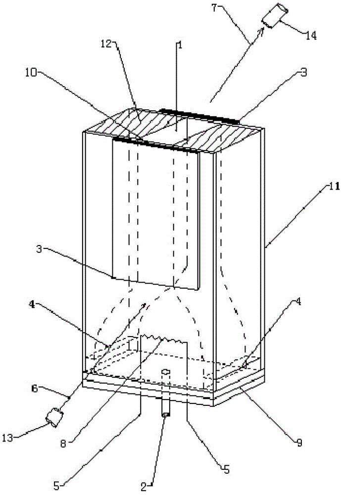
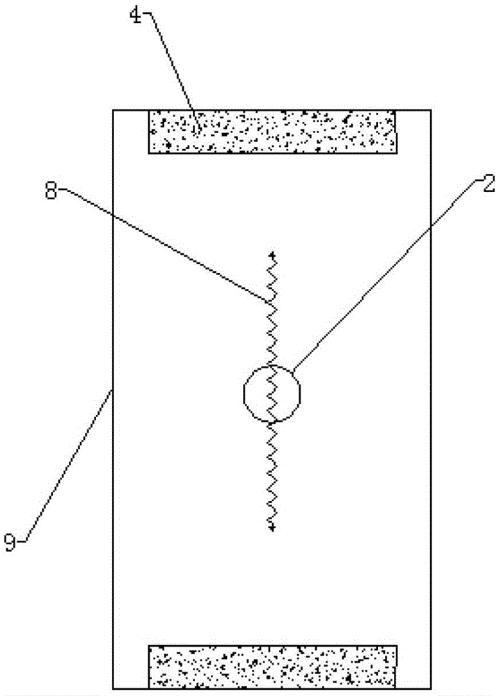
[0038] Embodiment 1: as figure 1 As shown, the device is composed of quartz 12 (thickness 4mm) and flat quartz 11 (thickness 0.8mm, distance between two planes is 4mm), electrolytic chamber (4mm×50mm, upper bottom 6mm, lower bottom 12mm), the surface of the flat quartz 11 has a silver-plated surface 10 (8mm×80mm), the copper electrode plate 3 (1mm×10mm×70mm) is closely combined on the silver-plated surface 10, and the copper electrode plate 3 is connected to the high High-frequency high-voltage power supply (10KV, 10MHZ), heat-resistant glass bottom plate 9 has a sample inlet 2 (diameter 1mm), exhaust port 1 (diameter 2mm), heating wire 8 passes through the bottom plate 9 and connects to the wire 5, when electrolysis: Connect the two electrodes 4 to the DC power supply through wires, and connect the two ends of the heating wire 8 to the negative pole of the DC power supply through the wire 5; The lamp 13 generates incident light 6, which enters the dielectric barrier discharg...

Embodiment 2

[0042] Embodiment 2: as figure 1 As shown, the device is a discharge chamber (8mm×16mm×100mm) composed of heat-resistant glass 12 (thickness 8mm) and plane heat-resistant glass 11 (thickness 1mm, distance between two planes is 8mm), electrolytic chamber (8mm×60mm , upper bottom 16mm, lower bottom 24mm), the surface of the flat quartz 11 has an aluminum-plated mirror 10 (18mm×110mm), the copper electrode plate 3 (1mm×20mm×100mm) is tightly combined on the mirror 10, and the copper electrode plate 3 is connected by a wire High-frequency high-voltage power supply (30KV, 40MHZ), heat-resistant glass bottom plate 9 has a sample inlet 2 (diameter 1mm), exhaust port 1 (diameter 2mm), heating wire 8 passes through the bottom plate 9 and connects to the wire 5, when electrolysis : Connect the two platinum-plated gold electrodes 4 to the DC power supply through wires, and connect the two ends of the heating wire 8 to the negative pole of the DC power supply through the wire 5; when heat...


PUM

PropertyMeasurementUnit
thicknessaaaaaaaaaa

Abstract

The invention discloses a method and a device for detecting micro-atomization / ionization. The method includes: allowing a sample to enter an electrolytic cavity, allowing to-be-detected elements to deposit on an electric heating wire under electrolysis, discharging waste liquid, drying the electrolytic cavity with heating of the electric heating wire under the help of carrier gas, allowing gradual temperature rising of the electrolytic cavity until high-temperature evaporation and atomization are completed, by the carrier gas, loading to-be-detected atom vapor to a dielectric barrier discharge cavity, allowing incident light to shoot in an inclined angle after plasma is generated, allowing the incident light to reflect on a reflector in the dielectric barrier discharge cavity for multiple times, then allowing the incident light to obliquely shoot out from a carrier gas port, allowing the light shot out to be received by a detector, and detecting signals. Optical path length can be adjusted according to needs by adjusting incidence angle. Due to the fact that the incident light shoots out obliquely, background light interference caused by discharge can be avoided effectively. The device is simple in structure, small in size, low in working conditions, high in atomization efficiency, high in flexibility, good in stability and wide in application range, and miniaturization, automation and portability of analyzing instruments are facilitated.

Description

technical field [0001] The invention relates to a miniature atomization / ionization detection device and a method thereof, belonging to the technical field of instrument analysis. Background technique [0002] Sample introduction technology has always been the "bottleneck" that limits the sensitivity improvement of atomic spectrometry, and is the most active and important research field in the development of atomic spectrometry. Now it mainly includes pneumatic atomization method, ultrasonic atomization method, thermal atomization method, suspension atomization method, high pressure atomization method and electrospray method. Pneumatic atomization mainly has obvious defects in atomization efficiency, high salt resistance and memory effect; ultrasonic atomization has high cost and large matrix effect, so it is necessary to have a desolvation auxiliary system, which is not conducive to the miniaturization of the instrument ; Thermal atomization has a high atomization efficienc...

Claims


Application Information

Patent Timeline
Patent Type & Authority Patents(China)
IPC IPC(8): G01N21/74G01N27/68
Inventor 洪陵成张欢
Owner HOHAI UNIV
Learn More