High power microwave radial line slit array antenna

A slot array antenna and high-power microwave technology, which is applied in the field of radiation antennas, can solve the problems that the volume and weight cannot meet certain weapon applications, and the compactness of high-power microwave antennas is not high, and achieve compact structure, small axial size, and suppression The effect of grating lobes

Inactive Publication Date: 2013-06-12
NAT UNIV OF DEFENSE TECH
View PDF6 Cites 30 Cited by
  • Summary
  • Abstract
  • Description
  • Claims
  • Application Information

AI Technical Summary

Problems solved by technology

[0005] The technical problem to be solved by the present invention is to overcome the shortcomings of existing high-power microwave antennas that are not compact enough,

Method used


Image

  • High power microwave radial line slit array antenna
  • High power microwave radial line slit array antenna
  • High power microwave radial line slit array antenna

Examples


Embodiment Construction

[0023] Implementation example one:

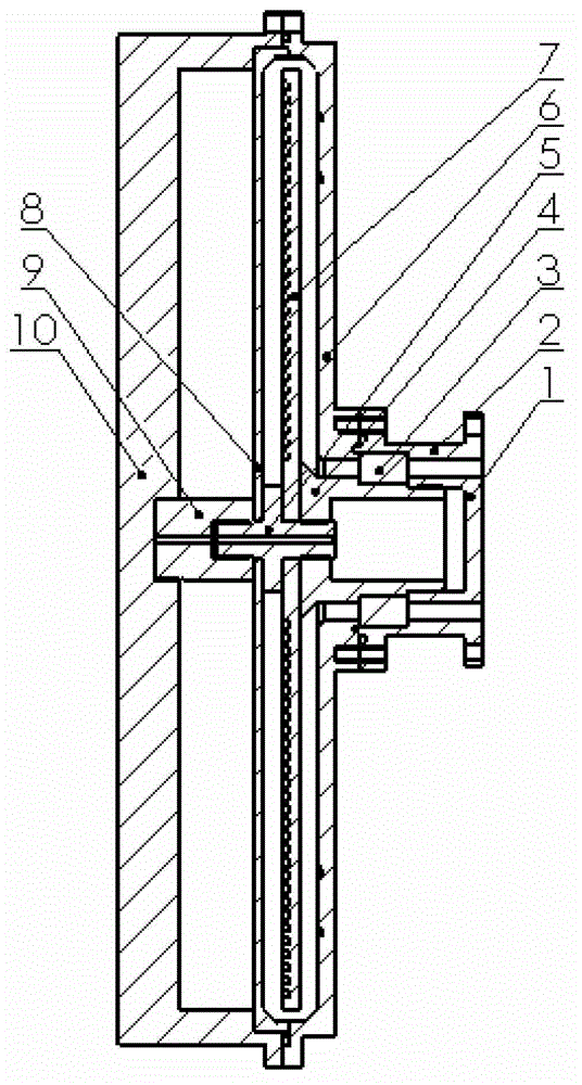
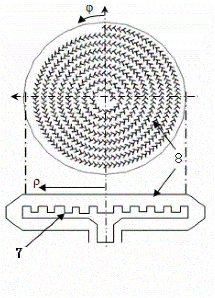
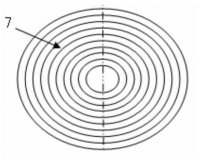
[0024] The high-power microwave radial line slot array antenna of the present invention comprises a coaxial input waveguide, a radial line leaky waveguide and a radome. The output port of the coaxial input waveguide is connected to the input port of the radial line leaky waveguide, and the output port of the radial line leaky waveguide is sealed by a radome. The coaxial input waveguide is composed of an input inner conductor 1, an outer conductor 2, a coaxial support rod 3 and an output inner conductor 4. The input inner conductor 1 is screwed to the output inner conductor 4, and the coaxial support rod 3 is clamped. The radial line leaky waveguide is composed of an axis support rod 5 , a leaky wave waveguide bottom plate 6 , a radial line slow wave structure 7 and a slot array mouth surface 8 . The axis support rod 5 is threadedly connected with the output inner conductor 4 of the coaxial input waveguide, and the radial line leaky wavegui...


PUM


Abstract

The invention relates to a high power microwave radial line slit array antenna which comprises a coaxial input waveguide, a radial line leaky wave waveguide and an antenna housing, wherein an output port of the coaxial input waveguide is connected with an input port of the radial line leaky wave waveguide, and an output port of the radial line leaky wave waveguide is sealed through the antenna housing. Microwaves are inputted through a coaxial over-mode waveguide in a transverse electronic and magnetic (TEM) mode, folding conversion is carried out through a double layer radial line waveguide, and microwave radial inner feedback is achieved on a waveguide upper layer. Slit unit arrays arranged on an antenna aperture cut a radial electric field, distant field same-phase superimposed circular polarization radian is achieved, the whole axial dimension is small, and the structure is compact. Due to action of a radial line slow wave structure, the wavelength of the radial line waveguide is reduced, and generation of slit array grating lobes is restrained. Due to the fact that a high order reflection mode excited by a wide slit array is restrained through a reflection offset spiral groove in a lower layer waveguide, the whole antenna has high radiant efficiency. Due to the improvement on the slit unit structure and vacuum sealing of the antenna housing, the whole radiating system has high power capacity, and application requirements in the high power microwave field can be met.

Description

technical field [0001] The invention relates to a radiation antenna in the technical field of high-power microwaves, in particular to a high-power microwave radial line slot array antenna working in a high-frequency band. Background technique [0002] In recent years, the attractive prospect of high-power microwave (according to the agreement of Benford and Swegle, high-power microwave refers to the electromagnetic wave with a peak power greater than 100MW and a frequency between 1 and 100GHz) in many fields has attracted widespread attention in many countries and a large number of Research has been invested and great technological progress has been made. At present, a variety of high-power microwave applications have been proposed: high-power microwave directed energy weapons, energy supply for satellites and space platforms, launch of small deep space probes, altitude change propulsion systems for orbiters, etc. So far, the research results of high-power microwave sources...

Claims


Application Information

Patent Timeline
IPC IPC(8): H01Q21/00H01Q13/10H01Q1/42
Inventor 袁成卫彭升人张强
Owner NAT UNIV OF DEFENSE TECH
Why Eureka
Try Eureka