S<4>R-type power supply control device

A power control device and charging control technology, applied in circuit devices, battery circuit devices, current collectors, etc., can solve the problems of low performance, heavy weight and large volume, and achieve the effect of high performance, light weight and small volume

Inactive Publication Date: 2013-06-12
HARBIN INST OF TECH
View PDF2 Cites 10 Cited by
  • Summary
  • Abstract
  • Description
  • Claims
  • Application Information

AI Technical Summary

Problems solved by technology

[0003] The present invention proposes a S 4 R type power control device

Method used


Image

  • S&lt;4&gt;R-type power supply control device
  • S&lt;4&gt;R-type power supply control device
  • S&lt;4&gt;R-type power supply control device

Examples


specific Embodiment approach 1

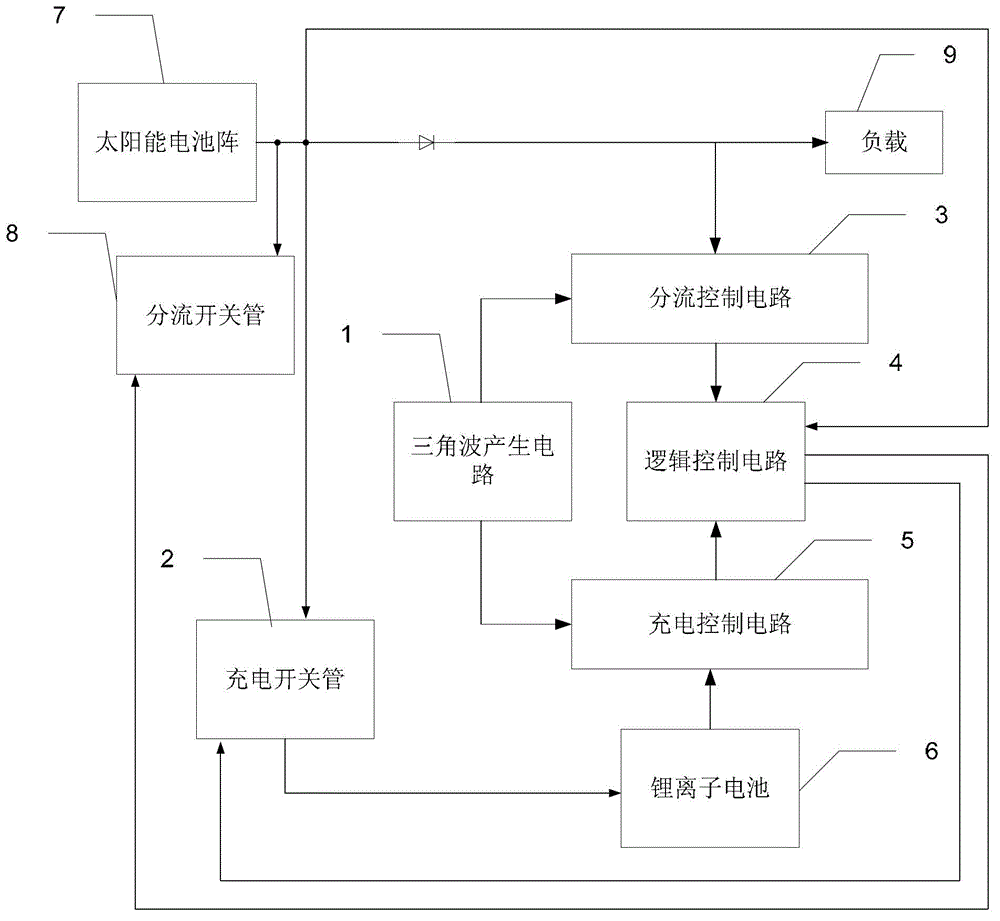
[0044] Specific implementation mode 1. Combination figure 1 Specifically describe this embodiment, a kind of S described in this embodiment 4 The R-type power supply control device includes a first diode, a triangular wave generating circuit 1, a charging switch tube 2, a shunt control circuit 3, a logic control circuit 4, a charging control circuit 5, a lithium ion battery 6, a solar cell array 7, and a shunt switch tube 8 and load 9,

[0045] The solar battery array 7 simultaneously sends the voltage signal to the charging switch tube 2, the logic control circuit 4 and the shunt switch tube 8,

[0046] The solar battery array 7 sends the first voltage signal to the shunt control circuit 3 and the load 9 simultaneously through the first diode,

[0047] The triangular wave generating circuit 1 sends the first triangular wave signal to the shunt control circuit 3 and the second triangular wave signal to the charging control circuit 5 respectively,

[0048] The shunt control ...

specific Embodiment approach 2

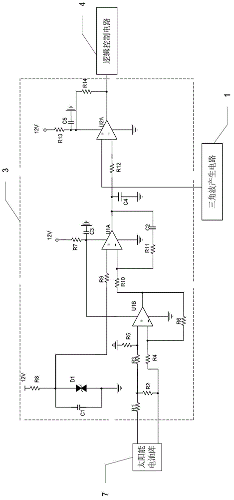
[0056] Specific implementation mode two, refer to figure 2 Describe this embodiment, a kind of S described in this embodiment and specific embodiment 1 4 The difference between the R-type power supply control device is that the shunt control circuit 3 includes resistors R1 to R14, capacitors C1 to C5, a first bi-phase voltage regulator diode D1, a first operational amplifier U1B, a second operational amplifier U1A and a third Operational amplifier U2A,

[0057] One end of the resistor R1 is connected to the positive pole of the solar cell array 7, and the other end of the resistor R1 is connected to one end of the resistor R2 and one end of the resistor R3 at the same time,

[0058] The other end of the resistor R2 is simultaneously connected with one end of the resistor R4 and the negative pole of the solar cell array 7,

[0059] The other end of the resistor R4 is simultaneously connected with one end of the resistor R6 and the negative phase input end of the first operat...

specific Embodiment approach 3

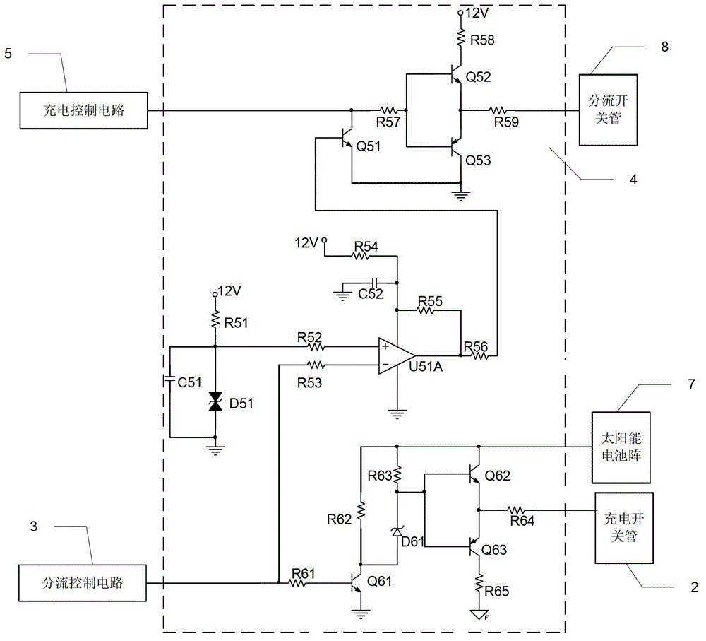
[0085] Specific implementation mode three, refer to image 3 Describe this embodiment, a kind of S described in this embodiment and specific embodiment 1 4 The difference between the R-type power supply control device is that the logic control circuit 4 includes resistors R51 to R59, resistors R61 to R65, capacitor C51, capacitor C52, a second dual-phase voltage regulator diode D51, a voltage regulator tube D61, a first NPN The transistor Q51, the second NPN transistor Q52, the first PNP transistor Q53, the third NPN transistor Q61, the fourth NPN transistor Q62, the second PNP transistor Q63 and the fourth operational amplifier U51A,

[0086] The second PWM signal output end of the charging control circuit 5 is simultaneously connected with one end of the resistor R57 and the collector of the first NPN transistor Q51,

[0087] The emitter of the first NPN transistor Q51 is connected to the collector of the first PNP transistor Q53, the collector of the first PNP transistor Q...


PUM


Abstract

The invention relates to an S<4>R-type power supply control device. The invention aims to solve the problems of a traditional power supply control device that the performance is poor, the weight is high and the size is large. Triangular wave signals with certain frequency are generated by a triangular wave generating circuit of the S<4>R-type power supply control device. A first voltage signal sent by a solar cell array is received by a shunting control circuit; the first voltage signal and a reference voltage signal are compared to generate a second voltage signal; and the second voltage signal and a first triangular wave signal generated by the triangular wave generating circuit are compared to generate a first PWM (pulse-width modulation) signal. A third voltage signal generated by a lithium ion battery is received by a charge control circuit; the third voltage signal and the reference voltage signal are compared to generate a fourth voltage signal; and the fourth voltage signal and a second triangular wave signal generated by the triangular wave generating circuit are compared to generate a PWM signal. A first switching signal or a second switching signal as well as a third switching signal or a fourth switching signal are generated by a logic control circuit. The S<4>R-type power supply control device is suitable for the field of control.

Description

technical field [0001] The invention relates to a power control device, in particular to a S 4 R type power control device. Background technique [0002] As a key technology of the satellite platform, the technical level of the power control device affects and restricts the development level of the satellite, and its performance, working life, weight and price have a significant impact on the overall design of the satellite. Due to the characteristics of high energy density, wide temperature range, low self-discharge rate, no memory effect, long charge and discharge life, and no pollution, lithium-ion batteries have become a new generation of energy storage power for space, which is very suitable for the development of space power. At the same time, in recent years, satellites have problems of low performance, heavy weight and large volume for power supply control devices. Contents of the invention [0003] The present invention proposes a S 4 R type power control devic...

Claims


Application Information

Patent Timeline
Patent Type & Authority Applications(China)
IPC IPC(8): H02J7/00
Inventor 林晓辉周明中邢雷陶建秋
Owner HARBIN INST OF TECH
Why Eureka
Try Eureka