

Hybrid power full hydraulic loading machine hydraulic system based on pressure common rail system
A common rail system, hybrid technology, applied in the direction of earth mover/shovel, construction, etc., can solve the problems of insignificant energy saving effect, low energy recovery rate of oil-electric hybrid system, etc., to improve fuel economy, Simple structure and low emission effect
- Summary
- Abstract
- Description
- Claims
- Application Information
AI Technical Summary
Problems solved by technology
Method used
Image

Examples
Embodiment approach
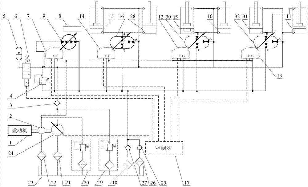
[0038] combined with figure 1 Describe the second specific embodiment of the present invention, the traveling hydraulic mechanism 9 includes a traveling hydraulic pump or a hydraulic motor; the traveling hydraulic mechanism control assembly 7 is mechanically connected to the traveling hydraulic mechanism 9, and the hydraulic transformer control assembly is mechanically connected to the hydraulic transformer; The hydraulic transformer includes a first hydraulic transformer 16, a second hydraulic transformer 30 and a third hydraulic transformer 32; the first hydraulic transformer 16 is connected to the boom oil tank, the second hydraulic transformer 30 is connected to the bucket oil tank, and the third hydraulic transformer The hydraulic transformer 32 is connected to the steering oil tank. Other components and connections are the same as those in the first embodiment. The boom oil tank includes the first boom oil tank 15 and the second boom oil tank 28; the bucket oil tank inc...
specific Embodiment approach
[0039] combined with figure 1 Describe the third specific embodiment of the present invention, the oil inlet port of the constant pressure variable pump 24 is connected to the oil tank 23 through the second filter 21; the oil inlet port of the quantitative pump 2 is connected to the oil tank 23 through the first filter 22; the second one-way The oil outlet port of the valve 27 is connected to the oil tank 23 through the fifth filter 18 , and the oil inlet port of the third check valve 25 is connected to the oil tank 23 through the sixth filter 26 . Other components and connections are the same as those in the first embodiment.
[0040] combined with figure 1 Describe the fourth specific embodiment of the present invention, the control input end of the constant pressure variable pump 24 is connected with the first control output end of the central controller 17, and the control input end of the electromagnetic reversing valve 6 is connected with the second control output end o...
PUM
 Abstract
Description
Claims
Application Information