Diode infrared detector readout integrated circuit with self-stabilization zero circuit

An infrared detector and readout circuit technology, applied in the direction of electrical radiation detectors, etc., can solve the problems of excessive DC offset, easy saturation of integral power, limited dynamic range, etc., to eliminate offset voltage and low-frequency noise, Eliminate offset voltage and low-frequency noise, improve integration and signal-to-noise ratio

Active Publication Date: 2013-06-19
中科芯未来微电子科技成都有限公司
View PDF8 Cites 0 Cited by
  • Summary
  • Abstract
  • Description
  • Claims
  • Application Information

AI Technical Summary

Problems solved by technology

However, there are problems such as excessive DC bias, which makes the integral capacitor easy to saturate, and the dynamic range is limited.
[0005] The bandwidth of the readout circuit of the diode infrared detector using the DC blocking circuit is limited, and the area is large
Although Mitsubishi's gate modulation circuit overcomes the problems of bandwidth and area, it has the problem that the integral circuit is easily saturated and the dynamic range is limited.
Neither the traditional readout circuit using a DC blocking circuit nor the gate modulation circuit of Mitsubishi Corporation has the function of eliminating the low-frequency noise of the circuit, which also limits the further improvement of the performance of the infrared detection system

Method used


Image

  • Diode infrared detector readout integrated circuit with self-stabilization zero circuit
  • Diode infrared detector readout integrated circuit with self-stabilization zero circuit

Examples


Embodiment Construction

[0019] The present invention will be further described below with reference to the specific drawings and embodiments.

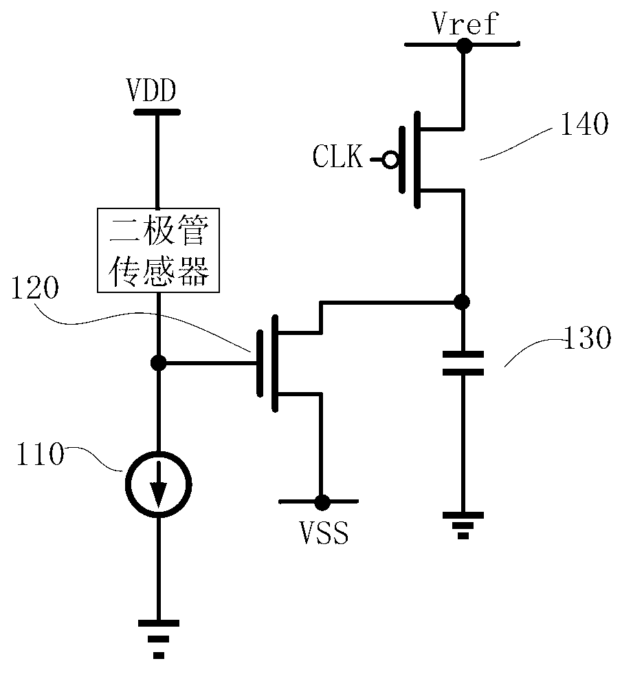
[0020] like figure 2 Shown: The PN junction of a diode-type uncooled infrared detector has good temperature characteristics, and its forward voltage decreases with increasing temperature. Therefore, the temperature change of the detector can be detected by measuring the change of the voltage drop across the diode, and then the intensity of the infrared radiation incident on the detector can be obtained. In order to overcome the problem of the conduction voltage drop of the diode infrared detector, eliminate the offset voltage and low-frequency noise, and improve the integration and signal-to-noise ratio of the system, the present invention includes a transistor 2 connected to the negative end of the diode infrared detector 1, and the The drain terminal of the transistor 2 is connected to the negative terminal of the diode infrared detector 1, and the source...


PUM


Abstract

The invention relates to a diode infrared detector readout integrated circuit with a self-stabilization zero circuit. The diode infrared detector readout integrated circuit comprises a transistor, wherein the drain end of the transistor is connected with the self-stabilization zero circuit; the self-stabilization zero circuit comprises a main operational amplifier and a secondary operational amplifier; the same-phase end of the main operational amplifier is connected with the phi 1 end of a first single-pole double-throw switch and the same-phase end of the secondary operational amplifier; the output end of the secondary operational amplifier is connected with the single end of a second single-pole double-throw switch; the phi 1 end of the second single-pole double-throw switch is connected with the first end of a secondary operational amplification capacitor and the auxiliary input end of a secondary operational amplifier; the second end of the secondary operational amplification capacitor is connected with the second end of a main operational amplification capacitor; and the first end of the main operational amplification capacitor is connected with the phi 2 end of the second single-pole double-throw switch and the auxiliary input end of a main operational amplifier. By the diode infrared detector readout integrated circuit, the problem of large breakover voltage drop in a diode infrared detector can be solved effectively, offset voltage and low-frequency noise are eliminated, and the integration level and signal to noise ratio of a system are improved; and the diode infrared detector readout integrated circuit is large in dynamic range, safe and reliable.

Description

technical field [0001] The invention relates to a circuit structure, in particular to a diode infrared detector readout circuit with a self-stabilizing zero point circuit, which belongs to the technical field of microelectronics. Background technique [0002] Infrared detection technology is increasingly widely used in military, space technology, medicine and related fields of national economy. Infrared detection chip is the core component of infrared detection technology to obtain infrared signal. This part consists of an infrared detector and a readout circuit (ROIC: readout integrated circuits). The basic function of the ROIC circuit is to convert, amplify and transmit the infrared detector signal. The readout circuit is the interface circuit between the infrared detector and the subsequent analog to digital converter (ADC: analog to digital convertor), and its performance directly affects the performance of the entire readout circuit. [0003] With the continuous expa...

Claims


Application Information

Patent Timeline
Patent Type & Authority Applications(China)
IPC IPC(8): G01J5/10
Inventor 黄卓磊王玮冰
Owner 中科芯未来微电子科技成都有限公司
Why Eureka
Try Eureka