Drive circuit of semiconductor optical amplifier
A technology for driving circuits and optical amplifiers, applied to semiconductor lasers, circuits, lasers, etc., can solve the problems of device electrical power changes, inability to provide constant current sources, device optical power changes, etc., and achieve the effect of maintaining stable electrical power
- Summary
- Abstract
- Description
- Claims
- Application Information
AI Technical Summary
Problems solved by technology
Method used
Image
Examples
Embodiment 1
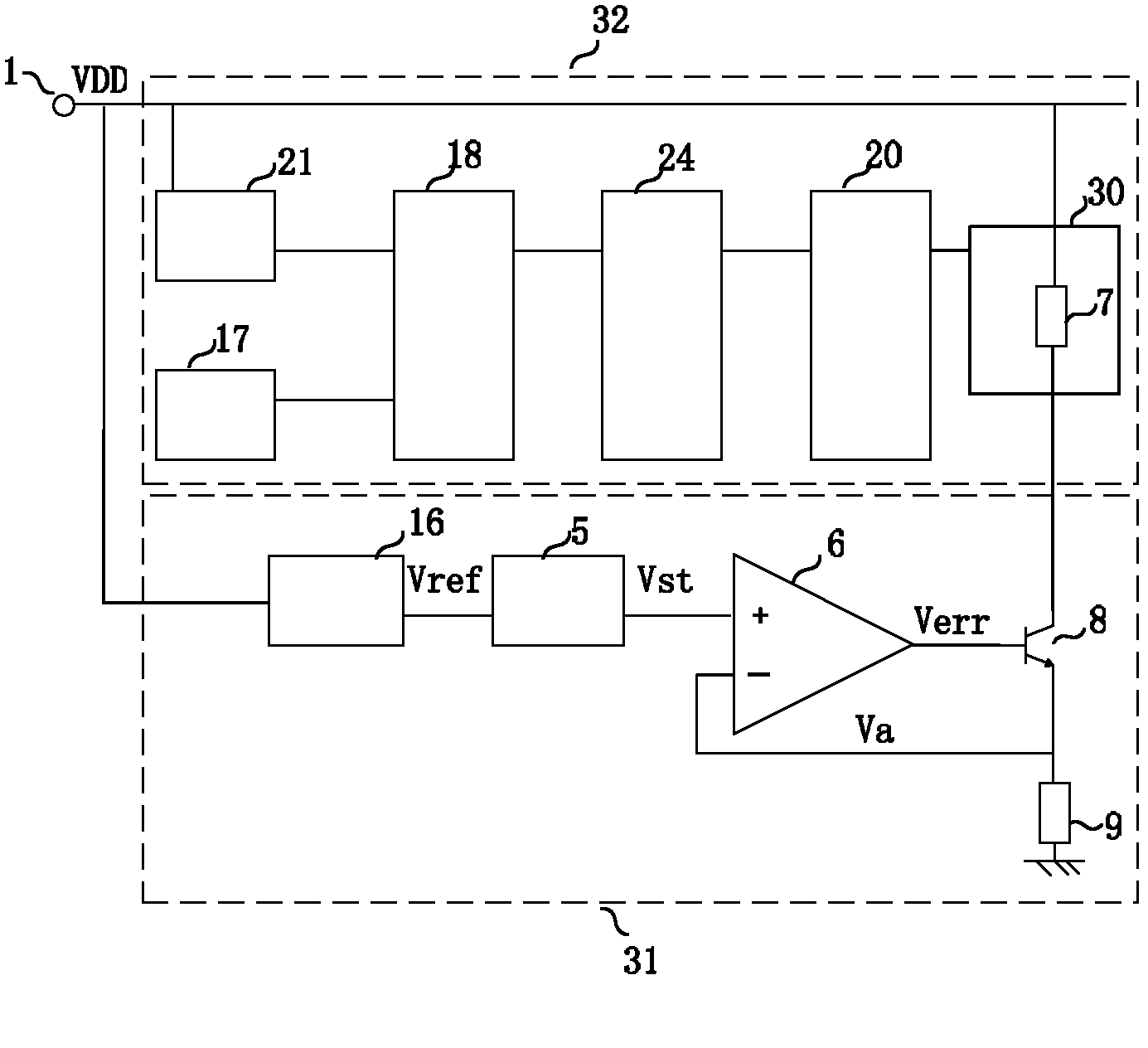
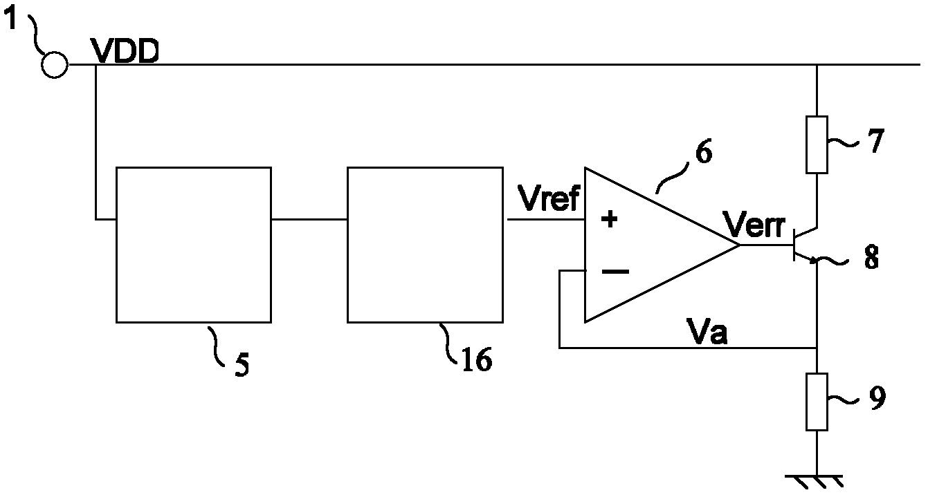
[0035] Figure 4 yes figure 2 The structural representation of the first embodiment of the constant current module in the drive circuit of the semiconductor optical amplifier shown; Figure 4, in this embodiment, the reference voltage circuit 16 is a sliding rheostat 4, the two ends of the sliding rheostat 4 are respectively connected to the power terminal 4 and the ground, and the sliding plate of the sliding rheostat 4 is connected to the slow start circuit 5, The slider end of the sliding rheostat 4 outputs a voltage reference Vref, which is processed by the slow start circuit 5 to output Vst. The non-inverting end of the operational amplifier 6 is connected to Vst, and the inverting end is connected to the end of the resistor 9 having a voltage value. The output of the operational amplifier output signal Verr is introduced through the connection of the inverting terminal of the operational amplifier. The collector of the transistor 8 is connected with the semiconductor...
Embodiment 2
[0039] Figure 5 yes figure 2 The structural representation of the second embodiment of the constant current module in the drive circuit of the semiconductor optical amplifier shown; Figure 5 , in this embodiment, the reference voltage circuit 16 is composed of a voltage regulator tube 12 and a high-precision resistor 11, the accuracy of the circuit is mainly determined by the precision of the resistor 11 and the voltage regulator tube 12, and the resistance accuracy should be less than one percent one. The high-precision resistor 11 is connected to VDD and the operational amplifier 10 through an upper terminal and a lower terminal, respectively. The voltage regulator tube 12 can better ensure the voltage reference and reduce the power consumption caused by directly dividing the voltage through the resistors. Since the load capacity of the front-stage voltage reference circuit is small, the input impedance and output impedance of the circuit can be adjusted through the fi...
Embodiment 3
[0041] Image 6 yes figure 2 The schematic structural view of the third embodiment of the constant current module in the driving circuit of the semiconductor optical amplifier shown; Composed of an operational amplifier 10, the configuration of the voltage reference is completed through digital control, and the personal computer 13 (host computer) sends control commands to the onboard processor 14 through some communication interface, such as USB, RS232, and Ethernet port, etc. , such as Arm, microcontroller, etc. The processor 14 then controls the digital-to-analog converter 15 through the board-level bus and sends voltage data to be converted. The output of the analog interface of the digital-to-analog converter is changed by programming the digital-to-analog converter 15 . After the analog output of the digital-to-analog converter, a first-stage operational amplifier 10 is required to enhance the load-carrying capability of the circuit. This structure can conveniently ...
PUM
 Abstract
Description
Claims
Application Information
 - R&D
- Intellectual Property
- Life Sciences
- Materials
- Tech Scout
- Unparalleled Data Quality
- Higher Quality Content
- 60% Fewer Hallucinations
Browse by: Latest US Patents, China's latest patents, Technical Efficacy Thesaurus, Application Domain, Technology Topic, Popular Technical Reports.
© 2025 PatSnap. All rights reserved.Legal|Privacy policy|Modern Slavery Act Transparency Statement|Sitemap|About US| Contact US: help@patsnap.com


