
Electromagnetic force actuator for active support of astronomical telescope mirror face

A technology of astronomical telescopes and force actuators, applied in telescopes, instruments, electrical components, etc., can solve problems such as reduced reliability, application limitations, and complex mechanical structures, and achieve coil power supply voltage reduction, output capability improvement, and high control accuracy Effect

Inactive Publication Date: 2013-06-26
NANJING INST OF ASTRONOMICAL OPTICS & TECH NAT ASTRONOMICAL OBSE
View PDF2 Cites 13 Cited by
  • Summary
  • Abstract
  • Description
  • Claims
  • Application Information

AI Technical Summary

Problems solved by technology

Pneumatic force actuators are also under active research. Electromechanical force actuators mainly realize linear displacement through the combination of stepper motor and ball screw, and realize precise output of force through compression spring or sealed bellows structure. The mechanical structure is relatively complex. Due to the influence of mechanical inertia and driving motor, the working frequency is generally difficult to reach above 1Hz. When used in low temperature environment, higher requirements are put forward for the lubrication of mechanical parts of the transmission system, and its reliability will be seriously reduced.
For the active optical force sensor of the space telescope, due to the limitation of the launch conditions, its weight is required to be as light as possible. Therefore, the application of the electromechanical force sensor in space is subject to certain restrictions
Piezoelectric force actuators mainly use the inverse piezoelectric effect of some dielectrics, that is, when an electric field is applied in the polarization direction of the dielectric, these dielectrics will deform. After the electric field is removed, the deformation of the dielectric will disappear, or called Although the electrostrictive phenomenon has the advantages of high precision and high frequency, it is difficult to overcome the shortcomings of high heat generation and low stroke, and its application is also severely limited in the Antarctic or space environments where energy consumption is limited.
Although the pneumatic force actuator has the advantages of high response frequency, high precision, low energy consumption, large stroke, etc., and can be used in the low temperature environment of Antarctica, but for the space vacuum environment, the pneumatic force actuator cannot work at all.

Method used


Image

  • Electromagnetic force actuator for active support of astronomical telescope mirror face

Examples


Embodiment 1

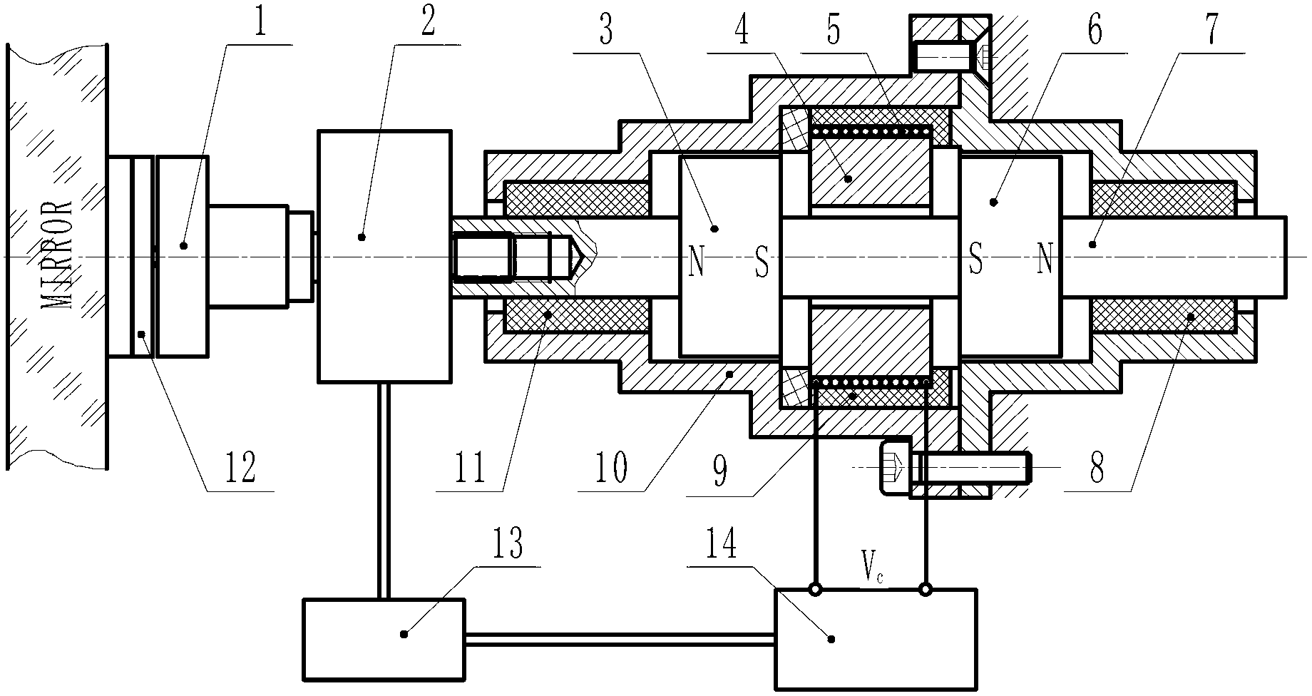
[0020] Embodiment 1, the electromagnetic force actuator structure is as figure 1 Shown. The second permanent magnet 3 and the third permanent magnet 6 are fixed on the shaft 7, and the two permanent magnets are opposite to each other with the same pole. The two ends of the shaft 7 are supported by low-friction materials 8, 11, and the left end of the shaft is connected to the force sensor 2 and connected to the mirror support pad 12 through the first permanent magnet 1. The support pad 12 is fixed to the bottom surface of the mirror by glueing. The coil 5 and the iron core 4 are installed and fixed in the housing 10 through an insulating material 9. When the coil 5 is not energized, the iron core 4 is under the combined action of the permanent magnets 6 and 7 on both sides and is in a balanced state. At this time, the force of the force actuator on the mirror surface is zero. When the coil 5 is energized, the coil 5 and the iron core 4 generate two magnetic poles. If a magnet...


PUM


Abstract

The invention relates to an electromagnetic force actuator for active support of an astronomical telescope mirror face. One end of the force actuator is connected with a supported mirror face through a force sensor, and the other end of the force actuator is fixed in a mirror cell. The electromagnetic force actuator is characterized in that a force output end of the force actuator is arranged on an axle at the center of the force actuator; two permanent magnets with strong magnetism are arranged on the center axle of the force actuator; a coil with an iron core is fixed on a shell of the force actuator; and the output of the force actuator is connected with a control system, and the control system is connected with the coil with the iron core. The electromagnetic force actuator for the active support of the astronomical telescope mirror face has the advantages that structure is simple, mass is low, energy consumption is low, control accuracy of input force is high, response speed is high, stroke of the force actuator is large, force adjusting range is wide, environment requirements are low, and the force actuator can be used in South Pole and even in space special environment. Connection of the force actuator and the mirror face is facilitated.

Description

Technical field [0001] The invention is a precise force output device, in particular to an electromagnetic force actuator for active support of the mirror surface of an astronomical telescope. This electromagnetic force actuator is mainly used in active optical mirror support technology for astronomical telescopes. Axial support for thin mirrors or lightweight mirrors, active optical correction and position adjustment of mirrors, can also be applied to the cutting of liquid crystal panels and other occasions that require high output force accuracy. Background technique [0002] Active optics technology is mainly to correct the mirror surface shape errors caused by the manufacturing, installation, gravity field, and temperature gradient of the telescope mirror. In the past two decades, active optics technology has been widely used in ground-based telescopes. Active optical support system is one of the key technologies in the design of large-aperture telescopes. As the most impo...

Claims


Application Information

Patent Timeline
Patent Type & Authority Applications(China)
IPC IPC(8): H02K33/18G02B23/02G02B26/08
Inventor 牛冬生
Owner NANJING INST OF ASTRONOMICAL OPTICS & TECH NAT ASTRONOMICAL OBSE
Learn More