Supercharge Your Innovation With Domain-Expert AI Agents!

Low-temperature deposition device and process for TCO film

A transparent conductive film and deposition device technology, which is applied in metal material coating process, ion implantation plating, coating, etc., can solve the problems of high power consumption, high equipment operation cost, glass breakage, etc., and achieve equipment failure rate Low cost, reduced processing cost, simplified equipment structure

Active Publication Date: 2013-07-03
广东腾胜科技创新有限公司
View PDF5 Cites 2 Cited by
  • Summary
  • Abstract
  • Description
  • Claims
  • Application Information

AI Technical Summary

Problems solved by technology

[0004] (1) Due to the high-temperature deposition process, the equipment needs to be equipped with a high-power heater, resulting in high power consumption and high equipment operating costs;
[0005] (2) Due to the high-temperature baking function of the equipment, a large amount of cost is increased
In addition, the existence of high temperature leads to a shortened life of the vacuum seal
Therefore, in order to reduce the failure rate of the equipment, various cooling components should be added in the equipment, which further increases the cost of the equipment;
[0006] (3) During the high-temperature heating process, the substrate will also have the problem of uneven film formation due to uneven heating, which reduces the qualified rate of the product
For glass substrates, in severe cases, the glass will be broken due to uneven high temperature, resulting in waste and equipment downtime.
[0007] (4) It is impossible to deposit high-quality transparent conductive films on the surface of heat-resistant materials (such as: PET films, etc.), which limits its application range

Method used


Image

  • Low-temperature deposition device and process for TCO film
  • Low-temperature deposition device and process for TCO film
  • Low-temperature deposition device and process for TCO film

Examples


Embodiment 1

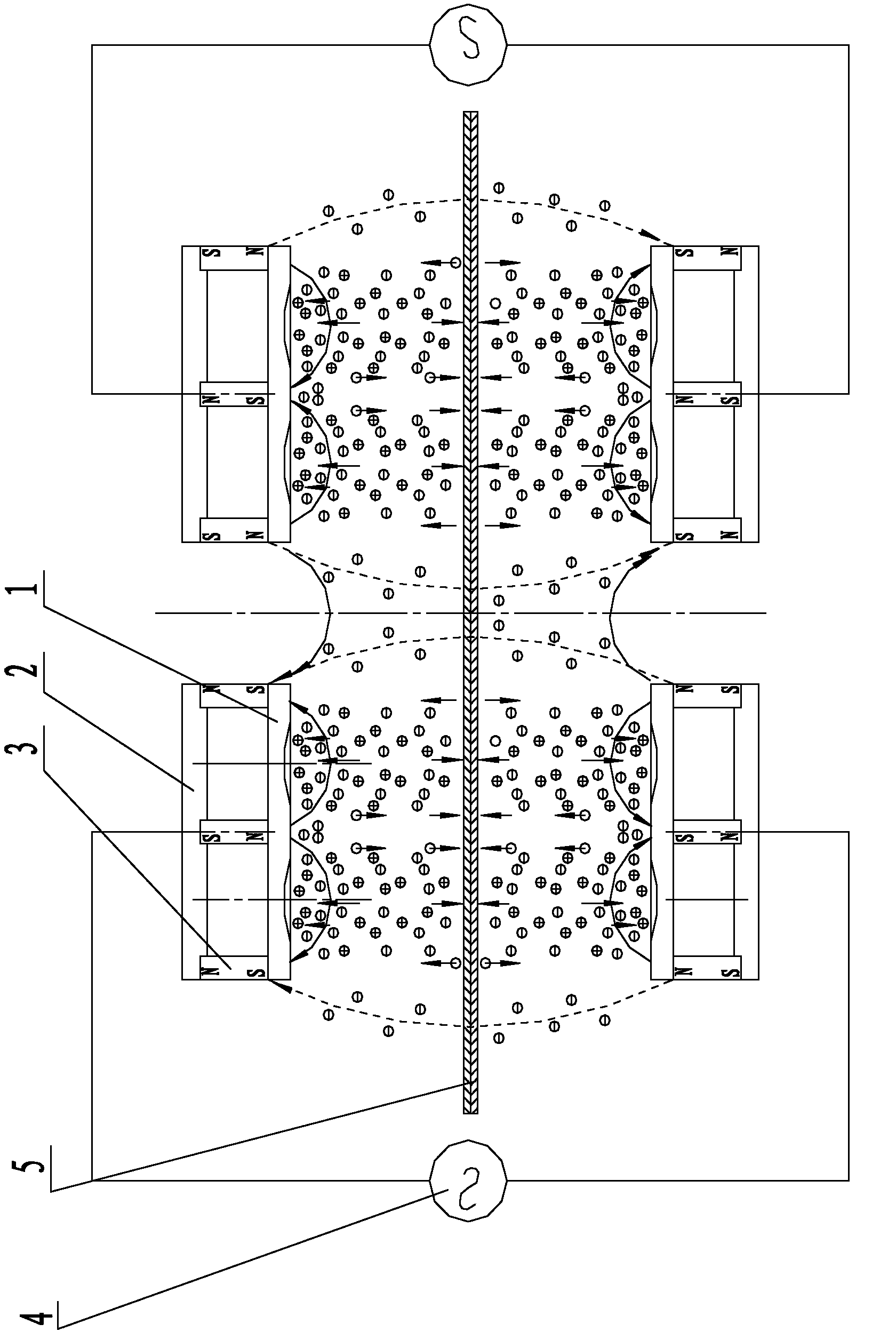
[0043]This embodiment is a low-temperature deposition device of a TCO transparent conductive film, which is used for simultaneously depositing coatings on both sides of a single glass substrate (such as figure 2 shown) or two glass substrates simultaneously deposited on one side (such as figure 1 shown).

[0044] The device includes multiple pairs of cathode groups arranged in the vacuum coating chamber, each pair of cathode groups is distributed on both sides of the substrate, and each pair of cathode groups is independently equipped with an intermediate frequency AC power supply or a bipolar pulse power supply 4; each pair of cathode groups includes two Each sputtering cathode comprises a target 1, a cathode body 2 and a magnet 3 respectively, the target is fixed on the cathode body, the cathode body is arranged on the side of the substrate, and a plurality of magnets distributed side by side are arranged in the cathode body, The two extreme faces of each magnet are vertic...

Embodiment 2

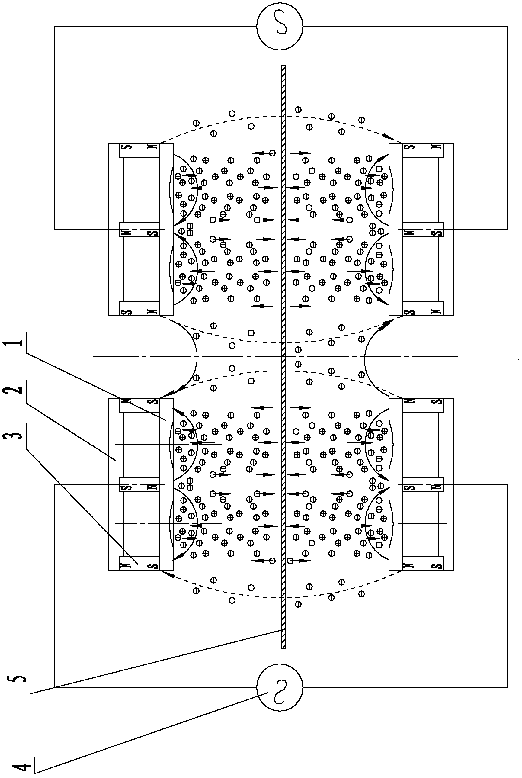
[0052] This embodiment is a low-temperature deposition device for a TCO transparent conductive film, which is used for depositing a coating film on one side of a single glass substrate.

[0053] like image 3 As shown, the device includes a pair of cathode groups arranged in the vacuum coating chamber. The cathode groups are distributed on one side of the substrate. The cathode groups are independently equipped with an intermediate frequency AC power supply or a bipolar pulse power supply 4; the cathode groups include two sputtering Cathode, each sputtering cathode comprises target material 1, cathode body 2 and magnet 3 respectively, target material is fixed on the cathode body, cathode body is arranged on the side of substrate, a plurality of magnets distributed side by side are arranged in cathode body, each magnet The two extreme faces are vertically connected with the target material and the magnetic block in the cathode body respectively; the magnetic polarity between tw...

Embodiment 3

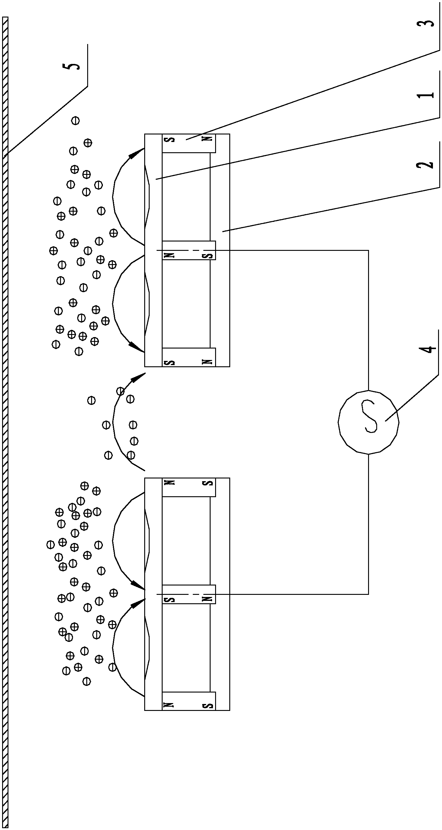
[0058] This embodiment is a low-temperature deposition device for TCO transparent conductive film, which is used for single-sided deposition and coating of flexible coils.

[0059] like Figure 4 As shown, the device includes multiple pairs of cathode groups located in the vacuum coating chamber, each pair of cathode groups is distributed on one side of the substrate, and each pair of cathode groups is independently equipped with an intermediate frequency AC power supply or bipolar pulse power supply 4; each pair of cathode groups Include two sputtering cathodes respectively, and each sputtering cathode includes a target 1, a cathode body 2 and a magnet 3 respectively, the target is fixed on the cathode body, the cathode body is arranged on the side of the substrate, and a plurality of side-by-side distributions are arranged in the cathode body The two pole faces of each magnet are vertically connected to the target material and the magnetic block in the cathode body respectiv...


PUM


Abstract

The invention discloses a low-temperature deposition device and process for a TCO (transparent conductive oxide) film. The device comprises at least one cathode assembly, wherein all the cathode assemblies are uniformly distributed on two sides of a substrate; each cathode assembly is independently provided with a medium-frequency power supply or a bipolar pulse power supply and comprises two sputtering cathodes; the sputtering cathodes comprise targets, cathode bodies and magnets respectively; the targets are arranged on two sides of the substrate, the cathode bodies are arranged on the outsides the targets, and a plurality of magnets which are distributed in parallel are arranged between the targets and the cathode bodies, and two ends of each magnet are connected with the targets and the cathode bodies respectively; and magnetic poles of one ends, connected with the targets, of every two adjacent magnets are opposite. The process comprises steps as follows: plasma areas are formed in the cathode assemblies respectively; the plasma areas cover sides of the substrate; electrons in the plasma areas oscillate at a high speed and continuously bombard the sides of the substrate; and a film layer deposited on the surface of the substrate is subjected to electron bombardment and surface heating treatment. According to the device and the process, TCO films of high quality are deposited at the normal temperature.

Description

technical field [0001] The invention relates to the technical field of coating of a TCO transparent conductive film, in particular to a low-temperature deposition device and process of a TCO transparent conductive film. Background technique [0002] TCO glass, that is, transparent conductive oxide coated glass, is a layer of transparent conductive oxide film uniformly coated on the surface of the flat substrate by physical or chemical coating methods, mainly including oxides of In, Sn, Zn and Cd and their Composite multi-element oxide film material. TCO glass mainly includes ITO coated glass, FTO coated glass and AZO coated glass. Among them, the development of ITO coated glass and FTO coated glass has been relatively mature. ITO coated glass has the characteristics of high light transmittance, firm film layer, and good conductivity. It is currently mostly used in the field of touch screens, but when used in solar cells, it is not stable enough in plasma, so it is not the ...

Claims


Application Information

Patent Timeline
Patent Type & Authority Applications(China)
IPC IPC(8): C23C14/35C23C14/08
Inventor 朱刚劲朱刚毅朱文廓江绍基
Owner 广东腾胜科技创新有限公司
Features
  • R&D
  • Intellectual Property
  • Life Sciences
  • Materials
  • Tech Scout
  • Unparalleled Data Quality
  • Higher Quality Content
  • 60% Fewer Hallucinations
Learn More