Lithium ion liquid flow battery
A flow battery, lithium ion technology, applied in the direction of regenerative fuel cells, battery pack components, circuits, etc., can solve the problems of battery short circuit, affecting battery safety performance and work efficiency, etc., to improve safety performance and cycle life, avoid Effect of Internal Short Circuit
- Summary
- Abstract
- Description
- Claims
- Application Information
AI Technical Summary
Problems solved by technology
Method used
Image
Examples
Embodiment 1
[0031] The present invention provides an embodiment of fixing the positive electrode layer:
[0032] The fixed positive electrode layer can be obtained by coating the mixture of positive electrode active material, conductive agent and binder on the porous substrate, and the specific process steps include:
[0033] 1) Lithium iron phosphate, carbon black, and polyvinylidene fluoride are mixed and dissolved in a certain amount of methylpyrrolidone organic solution according to the mass ratio of 7:2:1, and fully stirred evenly to prepare positive electrode slurry.
[0034] 2) Evenly coating the positive electrode slurry above on the foamed nickel substrate with a coating thickness of 100 microns.
[0035] 3) Drying the coated nickel foam substrate under the condition of 60° C. to 80° C. for 12 hours.
[0036] 4) Compacting the dried positive electrode slurry and the foamed nickel substrate under a pressure of 5MPa-20MPa to prepare a fixed positive electrode layer.
Embodiment 2
[0038] The present invention provides an embodiment of fixing the negative electrode layer:
[0039] The fixed negative electrode layer can be obtained by coating the mixture of negative electrode active material, conductive agent and binder on the porous substrate, and the specific process steps include:
[0040] 1) Lithium titanate, carbon black, and polyvinylidene fluoride are mixed and dissolved in a certain amount of methylpyrrolidone organic solution according to a mass ratio of 7:2:1, and fully stirred evenly to prepare negative electrode slurry.
[0041] 2) Coating the above-mentioned negative electrode slurry evenly on the porous polyolefin substrate with a coating thickness of 150 microns.
[0042] 3) Drying the coated porous polyolefin substrate under the condition of 60° C. to 80° C. for 6 hours.
[0043] 4) Compacting the dried positive electrode slurry and the porous polyolefin matrix under a pressure of 5MPa-20MPa to prepare a fixed negative electrode layer.
Embodiment 3
[0045] The present invention provides an embodiment of a lithium-ion flow battery:
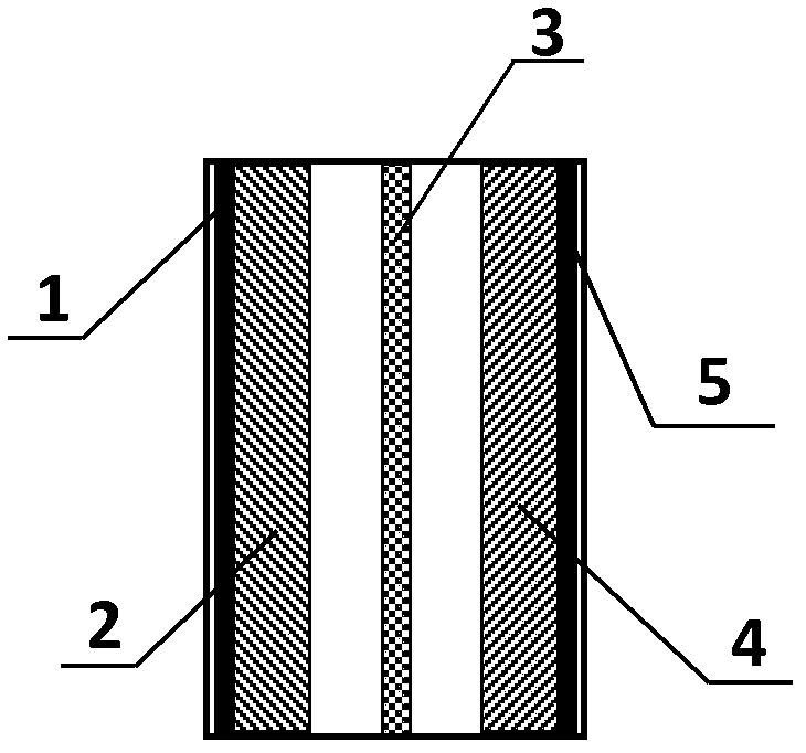
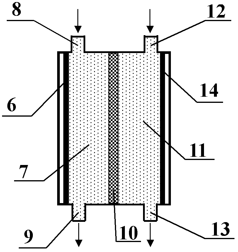
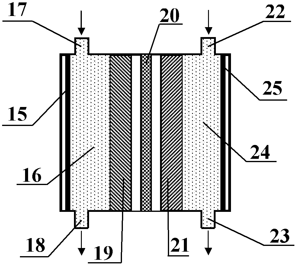
[0046] The lithium ion flow battery includes a positive electrode collector, a positive electrode reaction chamber, a positive electrode suspension, a fixed positive electrode layer, a porous diaphragm, a negative electrode reaction chamber, a negative electrode suspension, and a negative electrode collector. A fixed positive electrode layer is provided between the positive electrode reaction chamber and the porous diaphragm of the lithium ion flow battery, and electron conduction is performed between the fixed positive electrode layer and the positive electrode current collector through the positive electrode suspension.
[0047] The positive electrode current collector is metal aluminum foil, the positive electrode active material particles of the positive electrode suspension are lithium nickel manganese cobalt compound particles, the fixed positive electrode layer is a mixture of lithium ir...
PUM
| Property | Measurement | Unit |
|---|---|---|
| Thickness | aaaaa | aaaaa |
| Particle size | aaaaa | aaaaa |
Abstract
Description
Claims
Application Information
 - R&D
- Intellectual Property
- Life Sciences
- Materials
- Tech Scout
- Unparalleled Data Quality
- Higher Quality Content
- 60% Fewer Hallucinations
Browse by: Latest US Patents, China's latest patents, Technical Efficacy Thesaurus, Application Domain, Technology Topic, Popular Technical Reports.
© 2025 PatSnap. All rights reserved.Legal|Privacy policy|Modern Slavery Act Transparency Statement|Sitemap|About US| Contact US: help@patsnap.com


